Parallel active power filter system without electrolytic capacitor, and control method thereof

A power filter and control method technology, applied in active power filtering, control/regulation systems, instruments, etc., can solve the problems of reduced response speed, low cut-off frequency, and little effect, so as to improve the response speed and improve the response. effect of speed, increased reliability

Pending Publication Date: 2021-07-09
CHINA UNIV OF MINING & TECH
View PDF0 Cites 4 Cited by
  • Summary
  • Abstract
  • Description
  • Claims
  • Application Information

AI Technical Summary

Problems solved by technology

The amplitude of the voltage fluctuation on the DC side greatly affects the quality of the SAPF output current. In order to suppress the voltage fluctuation on the DC side, the traditional method is to connect a large-capacity electrolytic capacitor in parallel on the DC side of the SAPF to slow down the fluctuation, but there is an electrolyte in the electrolytic capacitor. Volatility and short life, especially when the fluctuating voltage is large, the fluctuating current repeatedly charges and discharges the electrolytic capacitor, which accelerates the aging of the capacitor and requires frequent replacement of the electrolytic capacitor, which affects the reliability of the device. At the same time, the large capacity The value of the electrolytic capacitor greatly affects the response speed of the DC side voltage
In addition, in order to avoid the impact of the fluctuation voltage on the DC side on the output current of the SAPF, a low-pass filter with a very low cut-off frequency needs to be added, which further reduces the response speed of the system
[0004] At present, some scholars have introduced a resonant controller to suppress the fluctuation of the SAPF DC side voltage, but the effect is very small, and it will also have a certain impact on the output current of the SAPF.

Method used


Image

  • Parallel active power filter system without electrolytic capacitor, and control method thereof
  • Parallel active power filter system without electrolytic capacitor, and control method thereof
  • Parallel active power filter system without electrolytic capacitor, and control method thereof

Examples


Embodiment Construction

[0034] The present invention will be further described below in conjunction with the accompanying drawings and specific embodiments. It should be understood, however, that the invention may be embodied in various forms, and some exemplary and non-limiting embodiments are shown in the drawings and described below, and are not intended to limit the invention to the specific embodiments described. .

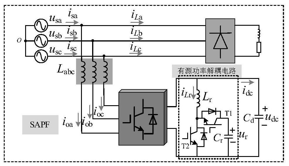
[0035] figure 2 Shown is the circuit topology of the parallel connection type SAPF system without electrolytic capacitors of the present invention, including three-phase power grid, harmonic load, filter inductor, two-level converter and bidirectional Boost active power decoupling circuit; the two-level converter The DC side uses a film capacitor C d ; The bidirectional Boost active power decoupling circuit specifically includes: two full-control switch tubes T1 and T2, a decoupling inductor L r and a film capacitor C r ; The T1 and T2 are connected in series, the other end of ...


PUM


Abstract

The invention discloses a parallel active power filter system without an electrolytic capacitor, and a control method thereof, and belongs to the field of power electronic control. The system comprises a three-phase power grid, a harmonic load, a filter inductor, a two-level converter and a bidirectional Boost active power decoupling circuit. The control method of the system comprises the following steps: step 1, completing alternating-current and direct-current side power exchange by controlling the two-level converter so as to realize load harmonic compensation; and step 2, by controlling the bidirectional Boost active power decoupling circuit, transferring the low-frequency fluctuation power of the direct current side of the active power filter to the auxiliary capacitor tosuppress the low-frequency ripple of the voltage of the direct current side of the active power filter. A thin-film capacitor with a small capacitance value can be used for replacing a traditional electrolytic capacitor under the condition that the voltage fluctuation of the direct current side is small, and the cost is reduced, so the system reliability is improved. In addition, a low-pass filter in a direct-current side voltage control link of the active power filter is omitted, and the corresponding speed of the system is increased.

Description

technical field [0001] The invention relates to the field of power electronic control, in particular to a non-electrolytic capacitor parallel-connected active power filter system and a control method. Background technique [0002] With the development of power electronics technology, many nonlinear loads in power distribution systems such as rectifiers, inverters, uninterruptible power supplies, and electric arc furnaces are increasing, and harmonic pollution in power grids is becoming increasingly serious. Harmonics can cause problems such as transformer overheating, protection equipment failure, harmonic resonance and communication network interference. In addition, with the development of technology and industry, large-capacity reactive devices such as high-power motors and transformers appear in power systems. Make the grid power factor low. Low power factor will lead to increased line loss, lower grid efficiency, and even grid collapse. The shunt active power filter (...

Claims


Application Information

Patent Timeline
Patent Type & Authority Applications(China)
IPC IPC(8): H02J3/01H02J3/18H02M3/158H02M1/088
CPCH02J3/01H02J3/18H02M1/088H02M3/1582Y02E40/20
Inventor 周娟徐高祥王莉原亚雷钊翔坤王梅鑫李京泽
Owner CHINA UNIV OF MINING & TECH
Why Eureka
Try Eureka