
High-viscosity battery slurry coating device and coating method thereof

A technology of coating device and coating method, which is applied in the direction of device and coating for coating liquid on the surface, can solve the problems of agglomeration of active material and conductive agent, increase the internal resistance of lithium battery, solvent recovery, etc., and reduce production. cost, the effect of reducing polarization and internal resistance, and reducing the degree of agglomeration

Pending Publication Date: 2021-07-13
般若涅利(北京)装备技术有限公司
View PDF0 Cites 0 Cited by
  • Summary
  • Abstract
  • Description
  • Claims
  • Application Information

AI Technical Summary

Problems solved by technology

[0005] However, the low-viscosity slurry (oily) also brings some negative effects, such as easy delamination, agglomeration of active materials and conductive agents, and increased internal resistance of lithium batteries.
After the coating is completed, all the solvent must be baked out when drying the pole piece, which also causes a series of cost problems such as high energy consumption and solvent recovery during drying.

Method used


Image

  • High-viscosity battery slurry coating device and coating method thereof
  • High-viscosity battery slurry coating device and coating method thereof
  • High-viscosity battery slurry coating device and coating method thereof

Examples


Embodiment 1

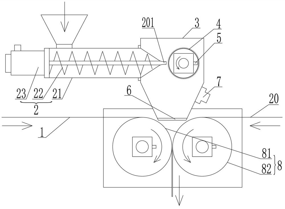
[0058] Example 1 High-viscosity battery slurry coating device

[0059] This example figure 1 As shown, a high-viscosity battery slurry coating device includes a coating counter-roll machine 8 for rolling the battery slurry on the current collector 1 and a coating counter-roll machine 8 for inputting the battery slurry into the coating counter-roll machine 8 The feeding device also includes an anti-sticking device to prevent the battery slurry from sticking to the coating roller machine 8 . The feeding device is a device for holding battery slurry, and the high-viscosity battery slurry is fed through the feeding device, so that the battery slurry enters the coating roller machine 8, and the battery slurry is coated by the coating roller machine 8. The material is coated on the current collector 1. During the coating process, the anti-sticking device can effectively prevent the battery slurry from sticking to the coating roller of the coating roller machine 8.

[0060] The fee...

Embodiment 2

[0065] Example 2 High-viscosity battery slurry coating device

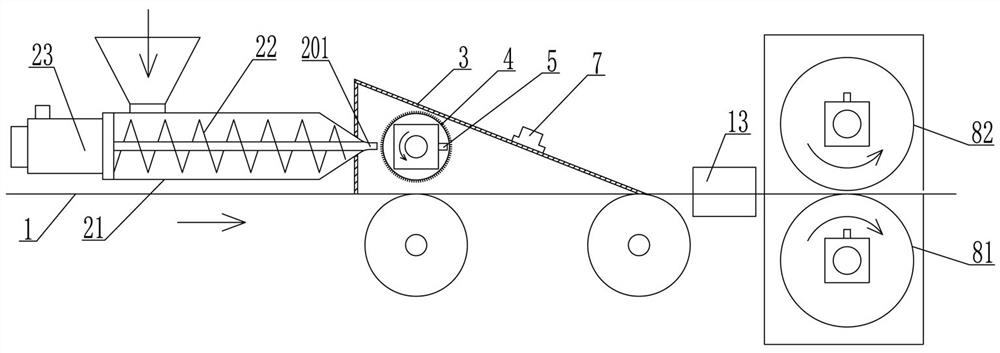
[0066] The structure of this embodiment is basically the same as that of Embodiment 1, the difference is the structure of the feed hopper 3, the arrangement of the feed hopper 3 and the structure of the anti-sticking device.

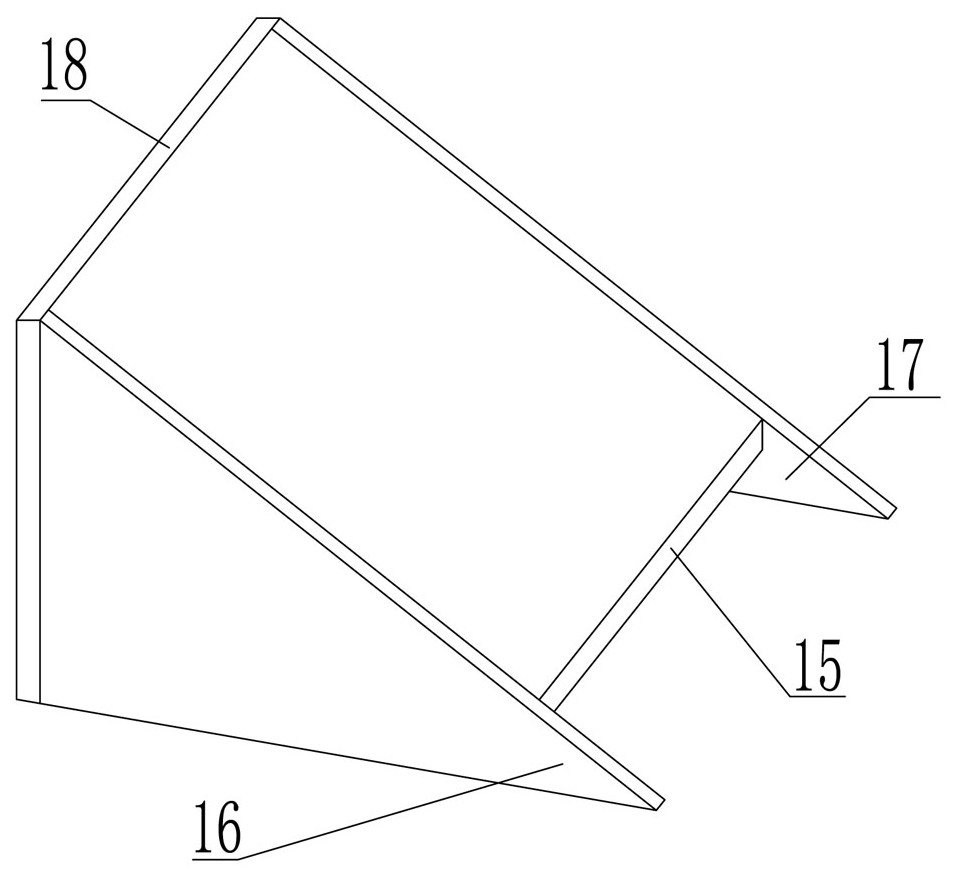
[0067] Such as figure 2 As shown, the feed hopper 3 of this embodiment is arranged parallel to the current collector 1, that is, the left and right direction of the feed hopper 3 is its length direction, and the length direction of the feed hopper 3 is the same as the movement direction of the current collector 1, as shown in image 3 As shown, the feed hopper 3 includes a first baffle 15 disposed opposite to the current collector 1 , a second baffle 16 and a third baffle 17 respectively fixed on both sides of the first baffle 15 . The first baffle plate 15 is inclined from high to low along the moving direction of the current collector 1, forming a slope. A gap is provided between the end...

Embodiment 3

[0070] Example 3 High-viscosity battery slurry coating device

[0071] The structure of this embodiment is basically the same as that of Embodiment 1, the difference is the structure of the feed hopper 3, the arrangement of the feed hopper 3 and the structure of the anti-sticking device.

[0072] Such as Figure 4 As shown, the feeding hopper 3 of this embodiment is arranged in parallel with the current collector 1, that is, the left and right direction of the feeding hopper 3 is its length direction, and the length direction of the feeding hopper 3 is the same as the moving direction of the current collector 1, so The feed hopper 3 is a shell, and the feed hopper 3 is also provided with a blocking roller 9 for preventing battery slurry from flying upwards. The blocking roller 9 is driven by a second motor 10. The gap between the wheels 4 is 0.1-5 mm, and the gap used in this embodiment is 3 mm, which can not only make the spur wheels 4 rotate normally, but also prevent the b...


PUM

PropertyMeasurementUnit
Viscosityaaaaaaaaaa
Thicknessaaaaaaaaaa
Penetrationaaaaaaaaaa

Abstract

The invention discloses a high-viscosity battery slurry coating device and a coating method thereof, and belongs to the field of battery preparation. The coating device comprises a coating double-roller machine and a feeding device, wherein the coating double-roller machine comprises a first coating roller used for bearing a current collector and a second coating roller used for compacting battery slurry, the feeding device comprises a feeding hopper and a conveying device used for conveying the battery slurry into the feeding hopper, the coating device further comprises an anti-sticking device used for preventing the battery slurry from sticking to the coating double-roller machine, and a scattering device for scattering battery slurry is arranged in the feeding hopper, The coating method comprises the following steps of preparing battery slurry with the viscosity of more than 10000 mPa.s or the penetration of 0.5-40 mm, conveying the battery slurry into the coating device at the pressure of 0.1-50 MPa, rotating and scattering the battery slurry, and coating the battery slurry on a current collector through the coating double-roller machine. According to the device and the method, the coating control precision is high, the production efficiency can be improved, the production cost can be reduced, meanwhile, the prepared lithium battery is small in polarization and ohmic internal resistance, the performance of the lithium battery is good, and the device and the method are suitable for coating all high-viscosity battery slurry.

Description

technical field [0001] The invention belongs to the technical field of battery preparation, and relates to a high-viscosity battery slurry coating device and a high-viscosity battery slurry coating method. Background technique [0002] The lithium battery coating method is an important process in the production of lithium batteries. Its purpose is to make the positive and negative electrode materials of the lithium battery into a slurry, uniformly coat and stick to the current collector to form a lithium battery pole piece. Lithium battery pole pieces are made into lithium batteries through key processes such as conventional rolling, slitting, winding or lamination, packaging, drying, liquid injection, formation, and standing. [0003] At present, the coating machines used in the lithium battery industry adopt the transfer or extrusion process to evenly coat the slurry on the current collector. This method has high requirements on the physical state of the slurry, such as th...

Claims


Application Information

Patent Timeline
IPC IPC(8): B05C1/08B05C11/10B05C9/14B05C11/02B05C19/04B05C11/00B05D1/28
CPCB05C1/0826B05C11/10B05C9/14B05C11/025B05C19/04B05C11/00B05D1/28Y02E60/10
Inventor 王俊勇张聪聪
Owner 般若涅利(北京)装备技术有限公司
Learn More