Turbine guide vane structure with rib upper through seam on trailing edge
A technology of turbine guide vanes and turbine blades, which is applied to the supporting elements of blades, engine elements, machines/engines, etc., can solve the problems of insufficient cooling, neglected cooling of partition ribs, and low cooling efficiency of the surface of partition ribs, etc. Effects of film cooling efficiency, good process integrity, good heat transfer and cooling characteristics
- Summary
- Abstract
- Description
- Claims
- Application Information
AI Technical Summary
Problems solved by technology
Method used
Image
Examples
Embodiment 1
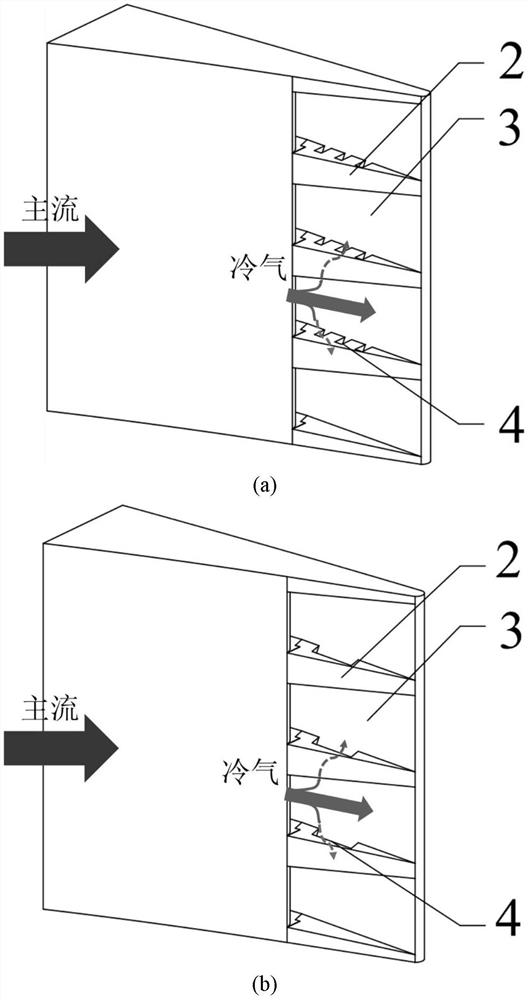
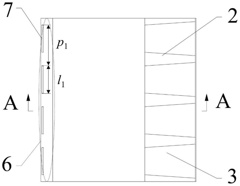
[0035] This embodiment is a certain type of turbine guide vane with ribs running through oblique slots on the trailing edge. The cooling air flows through the cold flow inlet 6 and enters the cooling structure of the turbine blade trailing edge with ribs passing through the oblique slots. The cooling air flows through the cold air outlet slots 7 Afterwards, a cooling air film is formed on the half-slit surface 3 of the trailing edge, thereby cooling the pressure surface 1 of the trailing edge of the blade. During the flow of the cold air to the downstream of the split, due to the effect of the three rectangular slits 4 on the partition rib, different The cooling air flow on the surface of the half-slit unit communicates through the oblique slots, which weakens the cold air vortex generated under the influence of the partition rib, weakens the interaction between the lip shedding vortex and the cold air vortex, and improves the film cooling efficiency on the surface of the partit...
Embodiment 2
[0037] This embodiment is a certain type of turbine guide vane with ribs running through oblique slots on the trailing edge. The cooling air flows through the cold flow inlet 6 and enters the cooling structure of the turbine blade trailing edge with ribs passing through the oblique slots. The cooling air flows through the cold air outlet slots 7 Afterwards, the cooling air film is formed on the half-slit surface 3 of the trailing edge, thereby cooling the pressure surface 1 of the trailing edge of the blade. During the flow of the cold air to the downstream of the split, due to the effect of the parallelogram oblique slit 4 on the partition rib, different half The cooling air flow on the surface of the split unit communicates through the oblique slots, which weakens the cold air vortex generated by the influence of the partition rib, weakens the interaction between the lip shedding vortex and the cold air vortex, and improves the air film cooling efficiency on the surface of the...
Embodiment 3
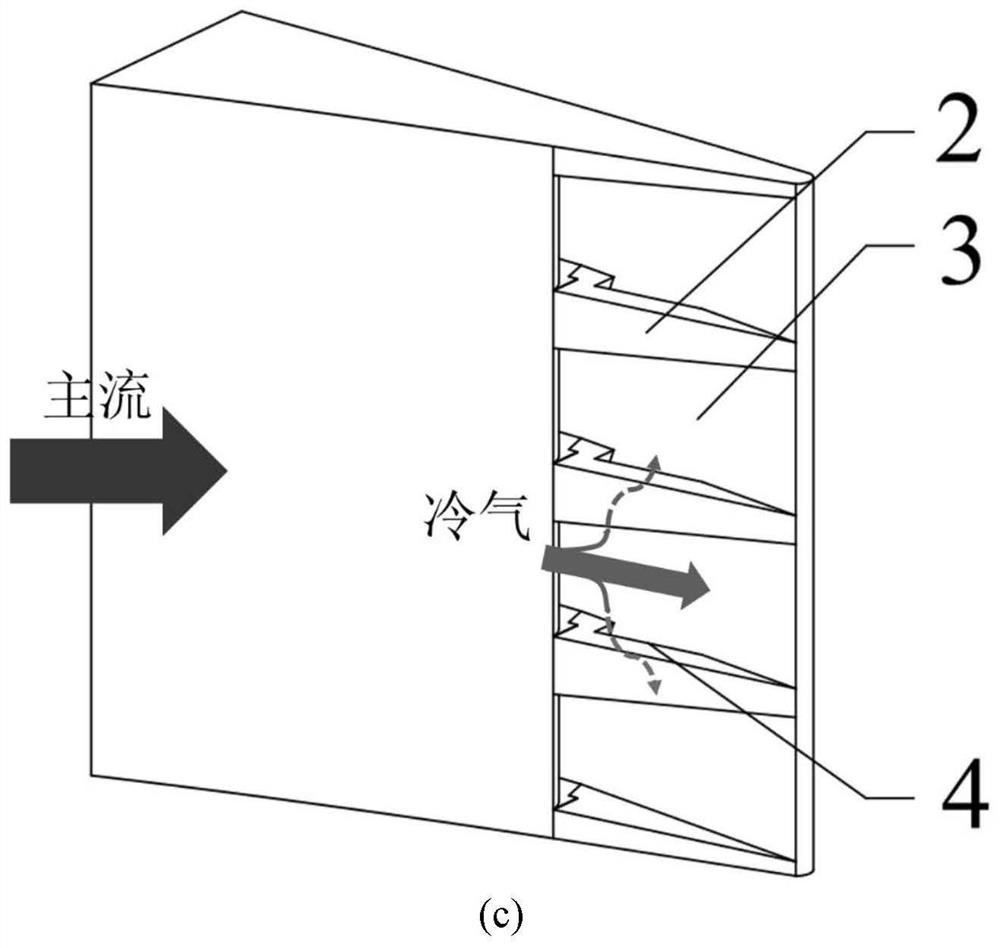
[0040] This embodiment is a certain type of turbine guide vane with ribs running through oblique slots on the trailing edge. The cooling air flows through the cold flow inlet 6 and enters the cooling structure of the turbine blade trailing edge with ribs passing through the oblique slots. The cooling air flows through the cold air outlet slots 7 Afterwards, the cooling air film is formed on the surface 3 of the half-slit at the trailing edge, thereby cooling the pressure surface 1 at the trailing edge of the blade. During the flow of the cold air to the downstream of the split, due to the effect of the triangular oblique slot 4 on the partition rib, different half-slits The cooling air flow on the surface of the slit unit communicates through the oblique slits, which weakens the cold air vortex generated by the influence of the partition rib, weakens the interaction between the lip shedding vortex and the cold air vortex, and improves the air film cooling efficiency on the surfa...
PUM
 Abstract
Description
Claims
Application Information
 - R&D
- Intellectual Property
- Life Sciences
- Materials
- Tech Scout
- Unparalleled Data Quality
- Higher Quality Content
- 60% Fewer Hallucinations
Browse by: Latest US Patents, China's latest patents, Technical Efficacy Thesaurus, Application Domain, Technology Topic, Popular Technical Reports.
© 2025 PatSnap. All rights reserved.Legal|Privacy policy|Modern Slavery Act Transparency Statement|Sitemap|About US| Contact US: help@patsnap.com


