
A sprinkling device for forcedly dispersing material powder by flue gas

A technology of forced dispersion and material spreading device, which is applied to the improvement of process efficiency, furnace, lighting and heating equipment, etc. It can solve the problems of limited effect, waste of high-temperature flue gas heat, and rapid wear, so as to reduce the possibility of failure, Long-term stable and reliable work, the effect of strengthening the dispersion effect

Active Publication Date: 2022-07-05
成都建筑材料工业设计研究院有限公司
View PDF1 Cites 0 Cited by
  • Summary
  • Abstract
  • Description
  • Claims
  • Application Information

AI Technical Summary

Problems solved by technology

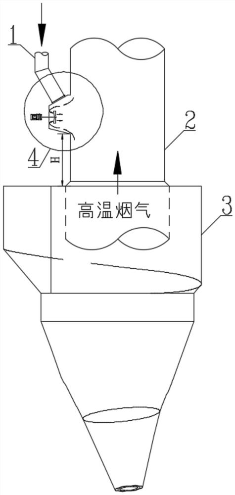
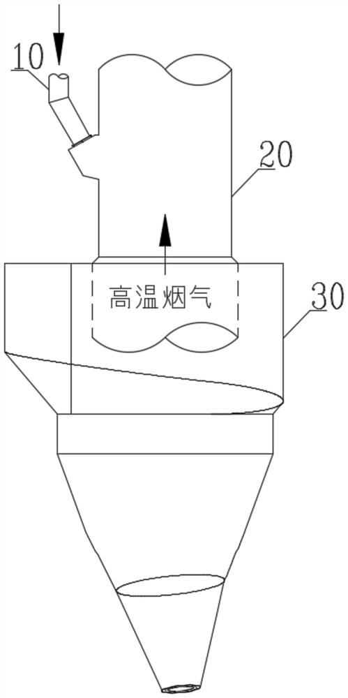
Or extend the bottom plate into the heat exchange pipe for a certain distance, and design a number of small holes evenly distributed in the protruding part to allow the high-temperature flue gas in the heat exchange pipe to pass through, so as to enhance the dispersion effect of the material powder. The above measures have not changed the material quality. The most fundamental driving force for powder dispersion still comes from the component force of the gravity of the powder itself along the direction of the material pipe, and the buoyancy force of the high-temperature flue gas in the heat exchange pipe to the powder, resulting in the effect of uniform dispersion of the powder in the high-temperature flue gas limited
This fundamentally limits the heat transfer efficiency of powder-high-temperature flue gas, and cannot efficiently recover waste heat from high-temperature flue gas
[0006] (2) Provide a certain flow rate and high flow rate compressed air to the bottom plate of the material spreading box at a suitable angle to enhance the dispersion effect of the material powder in the high-temperature flue gas of the heat exchange pipe. Although this method provides additional material powder dispersion power source, can significantly improve the dispersion effect of the powder, but the temperature of the compressed air is much lower than the high-temperature flue gas, and it will exchange heat with the high-temperature flue gas, thus wasting the heat in the high-temperature flue gas
However, due to the long-term high-speed rotation of the rotating blade and the complete contact with the material powder, rapid wear will inevitably occur, resulting in high failure rates and low operating rates.
[0008] The current technology is difficult to efficiently suspend and disperse the material powder in the high-temperature flue gas through the material spreading device in a stable and reliable manner, so as to greatly improve the convective heat transfer efficiency of the material powder-high-temperature flue gas, thereby achieving efficient recovery of flue gas waste heat and reducing clinker burning. The purpose of heat loss

Method used


Image

  • A sprinkling device for forcedly dispersing material powder by flue gas
  • A sprinkling device for forcedly dispersing material powder by flue gas
  • A sprinkling device for forcedly dispersing material powder by flue gas

Examples


Embodiment Construction

[0031] In order to make the purposes, technical solutions and advantages of the embodiments of the present invention clearer, the technical solutions in the embodiments of the present invention will be clearly and completely described below in conjunction with the embodiments of the present invention. Obviously, the described embodiments are part of the implementation of the present invention. way, not all implementations. Based on the embodiments of the present invention, all other embodiments obtained by those of ordinary skill in the art without creative efforts shall fall within the protection scope of the present invention. Thus, the detailed descriptions of embodiments of the invention provided below are not intended to limit the scope of the invention as claimed, but are merely representative of selected embodiments of the invention.

[0032] In the description of the present invention, it should be understood that the terms indicating the orientation or positional rela...


PUM


Abstract

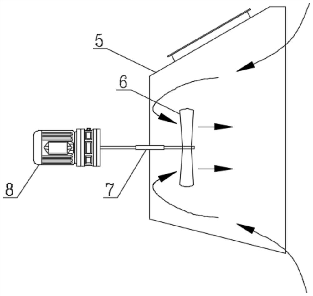
The invention relates to the technical field of gas-solid heat exchange in a preheating and pre-decomposition system, and specifically discloses a material spreading device for forcibly dispersing material powder by flue gas, comprising a material spreading mechanism, a feeding pipe connected to the inlet of the material spreading mechanism, and a material spreading device A heat exchange tube communicated with the outlet of the mechanism; the spreading mechanism includes a spreading shell provided with an inlet and an outlet, and a fan blade-type differential pressure generating mechanism installed in the spreading shell; the outlet of the spreading shell is connected to the heat exchange tube The side walls of the fan are connected to form a dispersion chamber, and the fan-blade differential pressure generating mechanism is located in the dispersion chamber; the rotation axis of the fan-blade differential pressure generating mechanism is not on the same line as the axis of the heat exchange tube. The invention can strengthen the dispersion effect of the material powder, without additional waste heat of the high-temperature flue gas, and at the same time, it can work stably and reliably for a long time.

Description

technical field [0001] The invention relates to the technical field of gas-solid heat exchange in a preheating and pre-decomposition system, and more particularly, to a material-spreading device for forcibly dispersing material powder with flue gas. Background technique [0002] As an important part of the preheating and pre-decomposition system, the spreading device plays a vital role in efficiently recovering the waste heat of the high-temperature flue gas from the powder, improving the heat exchange efficiency between the powder and the high-temperature flue gas, and reducing the heat consumption of clinker burning in the cement industry. . [0003] The traditional spreading device is mainly a spreading box (or called a spreading box), a spreading plate, etc., which are located at the appropriate position of the heat exchange pipes at the outlet of the preheater at all levels. The basic principles are as follows. figure 2 Shown: under the action of the component force of...

Claims


Application Information

Patent Timeline
Patent Type & Authority Patents(China)
IPC IPC(8): F27D17/00F27D13/00
CPCF27D17/004F27D13/00Y02P70/10
Inventor 汤跃刘建蔡顺华程宏伟
Owner 成都建筑材料工业设计研究院有限公司
Learn More