Forming device for metal parts

A molding device and metal parts technology, applied in the field of die-casting, can solve problems such as residue, unstable fluid state, poor mechanical properties of die-casting parts, etc., and achieve the effect of ensuring quality and pressure balance and stability

Active Publication Date: 2022-08-02
苏州圣美特压铸科技有限公司
View PDF7 Cites 0 Cited by
  • Summary
  • Abstract
  • Description
  • Claims
  • Application Information

AI Technical Summary

Problems solved by technology

[0003] In terms of technology, die-casting, like other manufacturing methods, also has some disadvantages: when die-casting is formed, the molten metal fills the cavity at a high speed, and the flow state is unstable. Into the molten metal and finally remain in the casting in the form of pores, and there are some oxide inclusions, which lead to defects such as poor mechanical properties of the die casting

Method used


Image

  • Forming device for metal parts
  • Forming device for metal parts
  • Forming device for metal parts

Examples


Embodiment 1

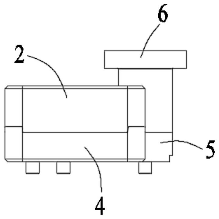
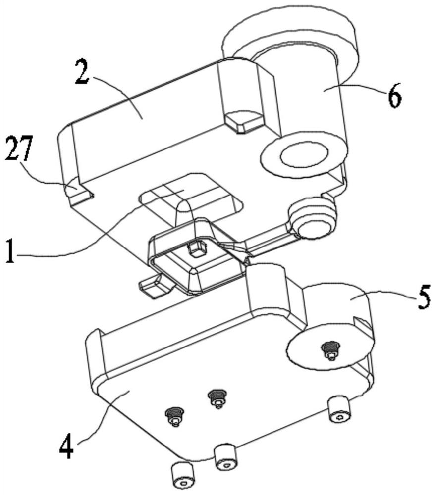
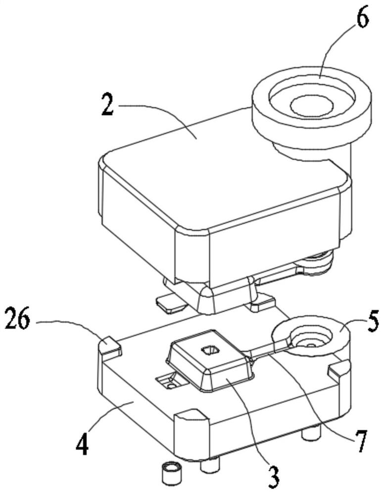
[0026] Embodiment 1: A molding device for metal parts, comprising an upper mold 2 with a cavity 1, a lower mold 4 with a core 3, a diverter cone 5 connected to one end of the lower die 4, and a diverter cone 5 connected to the diverter cone 5. Sprue sleeve 6, the upper end opening of the sprue sleeve 6 is connected to the die casting machine, the lower end of the sprue sleeve 6 is connected with the shunt cone 5 through, the upper surface of the lower mold 4 is located between the core 3 and the shunt cone 5 A first flow channel slot 7 is arranged between 5, and the first flow channel slot 7 is connected to the gap formed between the cavity 1 and the core 3;

[0027] The center of the upper surface of the core 3 has a concave portion 8, the core 3 also has a first through hole 9 penetrating through the concave portion 8, and a first through hole 9 is installed in the first through hole 9 that can be inserted into the first through hole. The first movable column 10 that moves u...

Embodiment 2

[0031] Embodiment 2: A forming device for metal parts, comprising an upper mold 2 with a cavity 1, a lower mold 4 with a core 3, a diverter cone 5 connected to one end of the lower die 4, and a diverter cone 5 connected to the diverter cone 5. Sprue sleeve 6, the upper end opening of the sprue sleeve 6 is connected to the die casting machine, the lower end of the sprue sleeve 6 is connected with the shunt cone 5 through, the upper surface of the lower mold 4 is located between the core 3 and the shunt cone 5 A first flow channel slot 7 is arranged between 5, and the first flow channel slot 7 is connected to the gap formed between the cavity 1 and the core 3;

[0032] The center of the upper surface of the core 3 has a concave portion 8, the core 3 also has a first through hole 9 penetrating through the concave portion 8, and a first through hole 9 is installed in the first through hole 9 that can be inserted into the first through hole. The first movable column 10 that moves u...


PUM


Abstract

The invention discloses a forming device for metal parts, which comprises an upper mold with a cavity, a lower mold with a core, a shunt cone connected to one end of the lower mold, and a gate sleeve connected with the shunt cone. The upper opening of the sleeve is connected to the die-casting machine, the lower end of the gate sleeve is connected to the shunt cone, and the upper surface of the lower mold is located between the core and the shunt cone. A first runner groove is provided. It communicates with the gap formed between the cavity and the core. A third cap body is fixedly connected to the lower surface of the shunt cone, the lower end of the third movable column is embedded in the third cap body, and a third elastic component is sleeved in the third cap body. The third movable column is located between the lower surface of the third flange portion and the third cap body. The present invention can monitor the pressure of the die-casting liquid entering the shunt cone through the deformation amount of the elastic component, thereby avoiding the problem of mold cracking and failure caused by excessive pressure of the die-casting liquid entering the mold, and prolonging the service life of the mold.

Description

technical field [0001] The invention relates to the technical field of die casting, in particular to a forming device for metal parts. Background technique [0002] In the field of die casting technology, die casting is a precision casting method that fills the molten alloy into the mold cavity at a high speed, and rapidly cools and solidifies the molten alloy under high pressure to achieve molding. As one of the advanced metal forming methods, die casting is an effective path to achieve less metal and no cutting in the field of modern metal forming technology. In addition, the die-cast metal parts are close to the final shape and size requirements. In mass production of complex structures. In terms of precision castings, it has unparalleled and unique advantages over other process methods. [0003] In terms of process, die casting, like other manufacturing methods, also has some disadvantages: when die casting is formed, the molten metal fills the cavity at a high speed, t...

Claims


Application Information

Patent Timeline
Patent Type & Authority Patents(China)
IPC IPC(8): B22D17/22B22D17/20
CPCB22D17/22B22D17/2272
Inventor 肖秀梅
Owner 苏州圣美特压铸科技有限公司
Why Eureka
Try Eureka