
Aerated concrete block preparation system and preparation process

A technology of air-entrained concrete and preparation system, which is applied in the direction of manufacturing tools, auxiliary molding equipment, molds, etc., can solve the problems of low production efficiency of aerated concrete blocks, increased equipment cost, and complicated disassembly process, so as to improve the use efficiency, Improve efficiency and quality, and ensure the effect of flush effect

Inactive Publication Date: 2021-07-16
王修东
View PDF6 Cites 3 Cited by
  • Summary
  • Abstract
  • Description
  • Claims
  • Application Information

AI Technical Summary

Problems solved by technology

[0004] In the existing process of preparing air-entrained concrete blocks, because the specifications of the air-entrained concrete blocks are different, the sizes are often different, so it is necessary to prepare multiple groups of molds with different specifications in advance according to the size of the prepared air-entrained concrete blocks. This will lead to an increase in the cost of manufacturing equipment
At the same time, after the air-entrained concrete block is dried, the mold needs to be disassembled, and most of the existing molds are integrated molding structures, and the disassembly process is extremely complicated, resulting in low production efficiency of the entire air-entrained concrete block

Method used


Image

  • Aerated concrete block preparation system and preparation process
  • Aerated concrete block preparation system and preparation process
  • Aerated concrete block preparation system and preparation process

Examples


Embodiment Construction

[0032] The technical solutions of the present invention will be further described in detail below in conjunction with the accompanying drawings and embodiments.

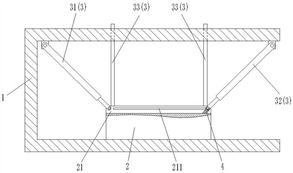
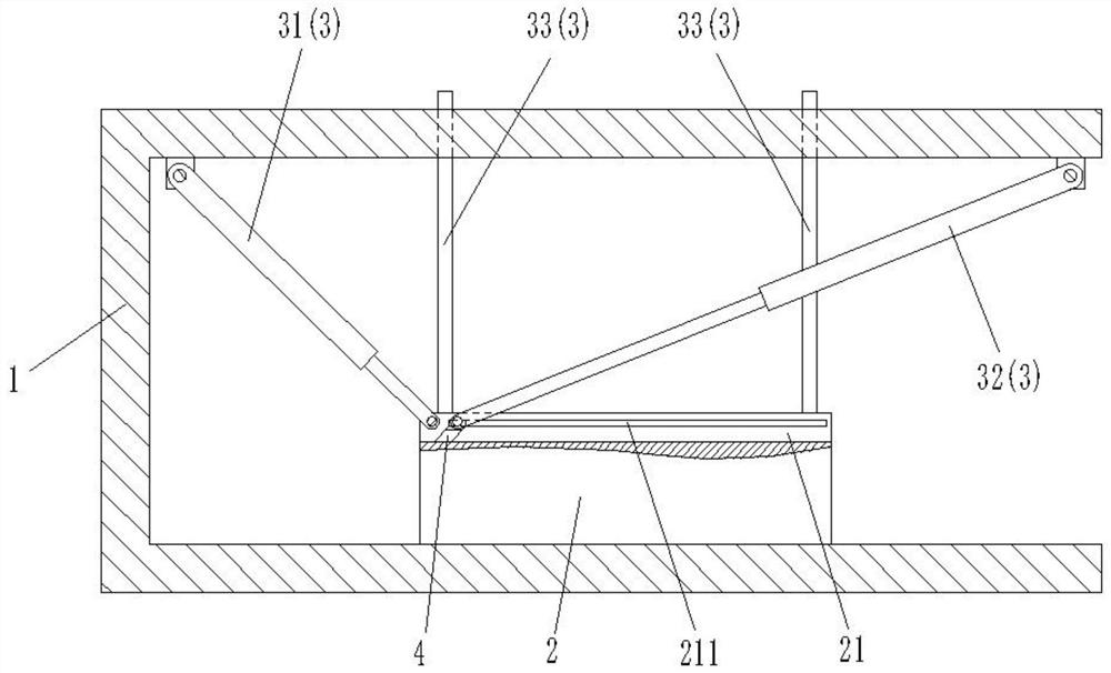
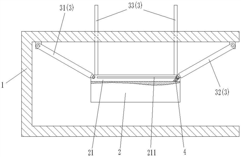
[0033] combine Figure 1 to Figure 6 As shown, the aerated concrete block preparation system of this embodiment includes a support 1 , a mold mechanism 2 and a lifting mechanism 3 . Wherein, the bracket 1 is a U-shaped structure, including an upper top and a lower bottom along the horizontal direction. The mold mechanism 2 and the lifting mechanism 3 are all located between the upper top and the lower bottom of the support 1, and one end of the lifting mechanism 3 is connected with the upper top of the support 1, and the other end is connected with the mold mechanism 2, so as to drive the mold mechanism 2 Vertical reciprocating movement is carried out between the upper top and the lower bottom of the support 1 .

[0034]In this embodiment, the mold mechanism 2 includes a mold frame 21 , a driving unit 22 , three co...


PUM


Abstract

The invention discloses an aerated concrete block preparation system which comprises a support, a mold mechanism and a lifting mechanism, wherein the mold mechanism comprises a mold frame, a driving unit, connecting rings, connecting rods, sliding rods and mold side plates; the connecting rings are positioned on the mold frame and can rotate; the driving unit drives the connecting ring to rotate; the multiple mold side plates are arranged in the connecting ring and are sequentially arranged in the circumferential direction of the connecting ring to define a mold cavity, and the adjacent mold side plates are in sliding connection; and the sliding rods are located between the connecting rings and the mold side plates and are in sliding connection with the mold frame in the radial direction of the connecting rings, one end of each sliding rod is in sliding connection with the corresponding mold side plate in the horizontal direction, the other end of each sliding rod is rotationally connected with one end of the corresponding connecting rod, and the other end of each connecting rod is rotationally connected with the corresponding connecting ring. According to the aerated concrete block preparation system, preparation of aerated concrete blocks of different sizes can be met, rapid demolding can be achieved, and the preparation efficiency and quality of the aerated concrete blocks are improved.

Description

technical field [0001] The invention belongs to the technical field of aerated concrete blocks, and in particular relates to a preparation system and a preparation process of aerated concrete blocks. Background technique [0002] Air-entrained concrete is made of siliceous materials (sand, fly ash and silicon-containing tailings, etc.) The lightweight porous silicate products made by processes such as pre-curing, cutting, autoclaving, and curing are named aerated concrete because they contain a large number of uniform and small pores after gasification. [0003] Air-entrained concrete is often used as a material for preparing air-entrained concrete blocks, and commonly used air-entrained concrete blocks are usually square structures, and such square-shaped air-entrained concrete blocks can be used as load-bearing blocks. Among them, when preparing the aerated concrete block, the concrete is generally poured into a special mold, and after various processes, the final aerated...

Claims


Application Information

Patent Timeline
IPC IPC(8): B28B1/50B28B13/06B28B7/38B28B1/14B28B7/02B28B7/00B28B17/00
CPCB28B1/50B28B1/503B28B13/06B28B7/382B28B1/14B28B7/02B28B7/0002B28B17/0081
Inventor 王修东杨延亮李贺
Owner 王修东
Learn More