Steel rail cambered surface grinding trolley and steel rail grinding wagon
A technology of rail grinding car and grinding trolley, which is applied in the direction of track, track laying, track maintenance, etc., can solve the problems of insufficient grinding of the rail profile surface, unable to pass through the switch area normally, limited grinding deflection angle, etc., and achieve self-sharpening. Good, simple structure, large grinding deflection angle
- Summary
- Abstract
- Description
- Claims
- Application Information
AI Technical Summary
Problems solved by technology
Method used
Image
Examples
Embodiment 1
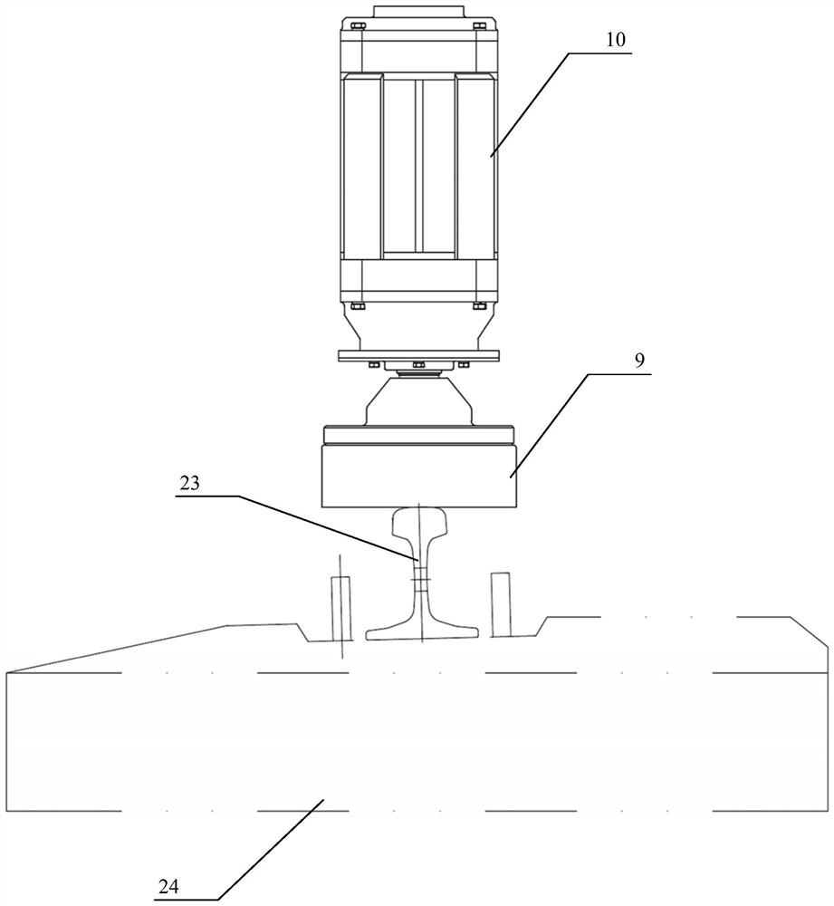
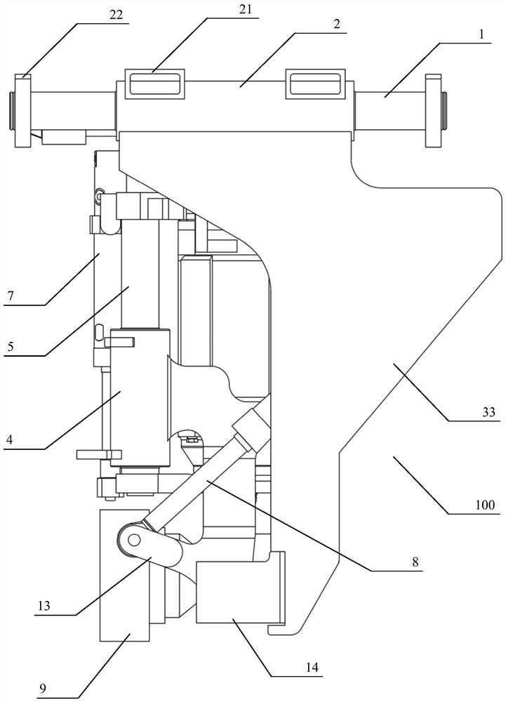
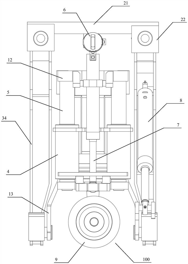
[0059] as attached figure 2 to attach Figure 12 As shown, an embodiment of the rail grinding unit 100 on which the present application is based specifically includes:
[0060] traverse mechanism;
[0061] Grinding motor 10, its output shaft links to each other with grinding wheel 9, and the steel rail 23 is polished by the outer circumference of grinding wheel 9;
[0062] It is used to install the grinding motor 10, and is movably connected to the grinding unit frame 3 of the traversing mechanism, and the traversing mechanism can drive the grinding motor 10 to realize the traversing operation;
[0063] The deflection mechanism connected between the grinding unit frame 3 and the grinding motor 10 can realize the deflection operation with the grinding motor 10 through the deflection mechanism;
[0064] And the pressing mechanism connected between the deflection mechanism and the grinding motor 10, the grinding motor 10 can be driven by the pressing mechanism to realize lift...
Embodiment 2
[0076] as attached Figure 15 to attach Figure 19 As shown, an embodiment of a rail arc grinding trolley 200 of the present application is arranged at the bottom of a rail grinding trolley 400, specifically comprising:
[0077] The vehicle frame 300, and the rail grinding unit 100 installed on the vehicle frame 300.
[0078] The rail grinding car 400 may further include:
[0079] One end is connected to the bottom of the rail grinding car 400, and the other end is connected to the lifting mechanism 28 of the vehicle frame 300;
[0080] The traction mechanism 29 that is installed on the bottom of the rail grinding car 400 and connected with the vehicle frame 300;
[0081] Installed on the vehicle frame 300 and arranged outside the fireproof and dustproof device 500 of the vehicle frame 300 , the rail grinding unit 100 is installed on the vehicle frame 300 and arranged inside the fireproof and dustproof device 500 .
[0082] The whole rail camber grinding trolley 200 includ...
Embodiment 3
[0090] as attached Figure 22 As shown, an embodiment of a rail grinding vehicle 400 of the present application specifically includes:
[0091] Body 600;
[0092] And be arranged on the lower part of the car body 600, such as the rail camber grinding trolley 200 described in Embodiment 2.
[0093] as attached Figure 17 And attached Figure 18 As shown, a door lock sensor 31 is installed on the frame 300 of the rail camber grinding trolley 200 , and a sensor induction plate 32 is installed on the door 26 of the fireproof and dustproof device 500 . When the car door 26 was opened, the sensor sensing plate 32 was far away from the door lock sensor 31, the rail grinding car 400 received the door lock signal, and the rail grinding car 400 was prohibited from running. When the car door 26 was closed, the sensor induction plate 32 was close to the car door lock sensor 31, and the rail grinding car 400 obtained the driving permission signal, and the rail grinding car 400 allowed ...
PUM
 Abstract
Description
Claims
Application Information
 - R&D
- Intellectual Property
- Life Sciences
- Materials
- Tech Scout
- Unparalleled Data Quality
- Higher Quality Content
- 60% Fewer Hallucinations
Browse by: Latest US Patents, China's latest patents, Technical Efficacy Thesaurus, Application Domain, Technology Topic, Popular Technical Reports.
© 2025 PatSnap. All rights reserved.Legal|Privacy policy|Modern Slavery Act Transparency Statement|Sitemap|About US| Contact US: help@patsnap.com


