Super-efficient environment-friendly new-energy closed-cycle high-power rotary jet engine
A new energy, closed-cycle technology, applied in the field of Stirling closed-cycle engines, external combustion engines, and internal combustion engines, it can solve the problems of unsatisfactory performance indicators and far from it, and achieve fuel versatility and environmental adaptability. , low-cost manufacturing, low-cost use
- Summary
- Abstract
- Description
- Claims
- Application Information
AI Technical Summary
Problems solved by technology
Method used
Image
Examples
Embodiment 1
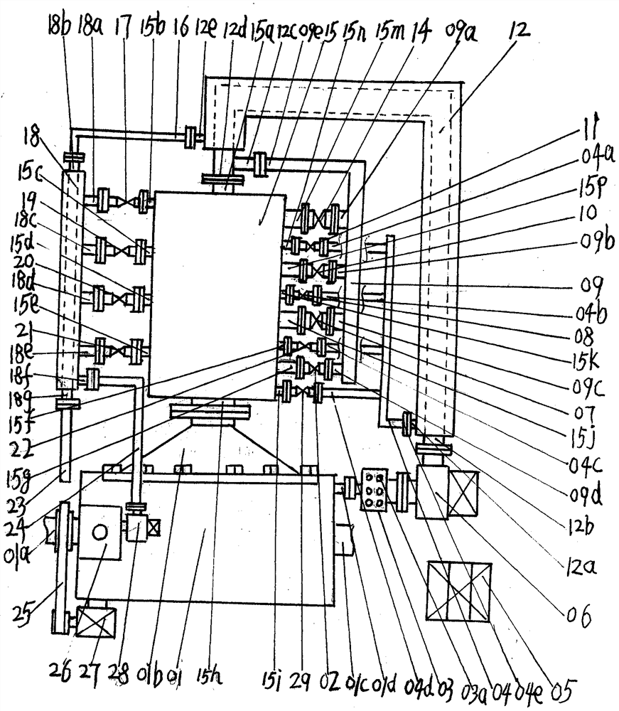
[0032] Such as figure 1As shown, an ultra-efficient and environmentally-friendly new energy closed-cycle high-power engine includes a jet jet machine 01, a multi-stage tubular burner 15, a generator 27, a supplementary supercharging and air intake electric air compressor 06, and a fuel tank 26 , the generator 27, the fuel tank 26, and the fuel delivery pump 28 are arranged and fixed on the fuselage of the rotary spray machine 01, and the rotary spray machine 01 includes a power output rear shaft head 01a, a heated medium intake flange interface 01b, a power The output front shaft head 01c, the medium exhaust gas outflow flange interface 01d, the medium exhaust gas outflow flange interface 01d and the power output front shaft head 01c are located on the right side of the rotary jet machine 01, close to the power output rear shaft head 01a side A fuel tank 26 and a generator 27 are installed and fixed on the fuselage of the rotary jet spray machine 01, and the generator 27 is co...
Embodiment 2
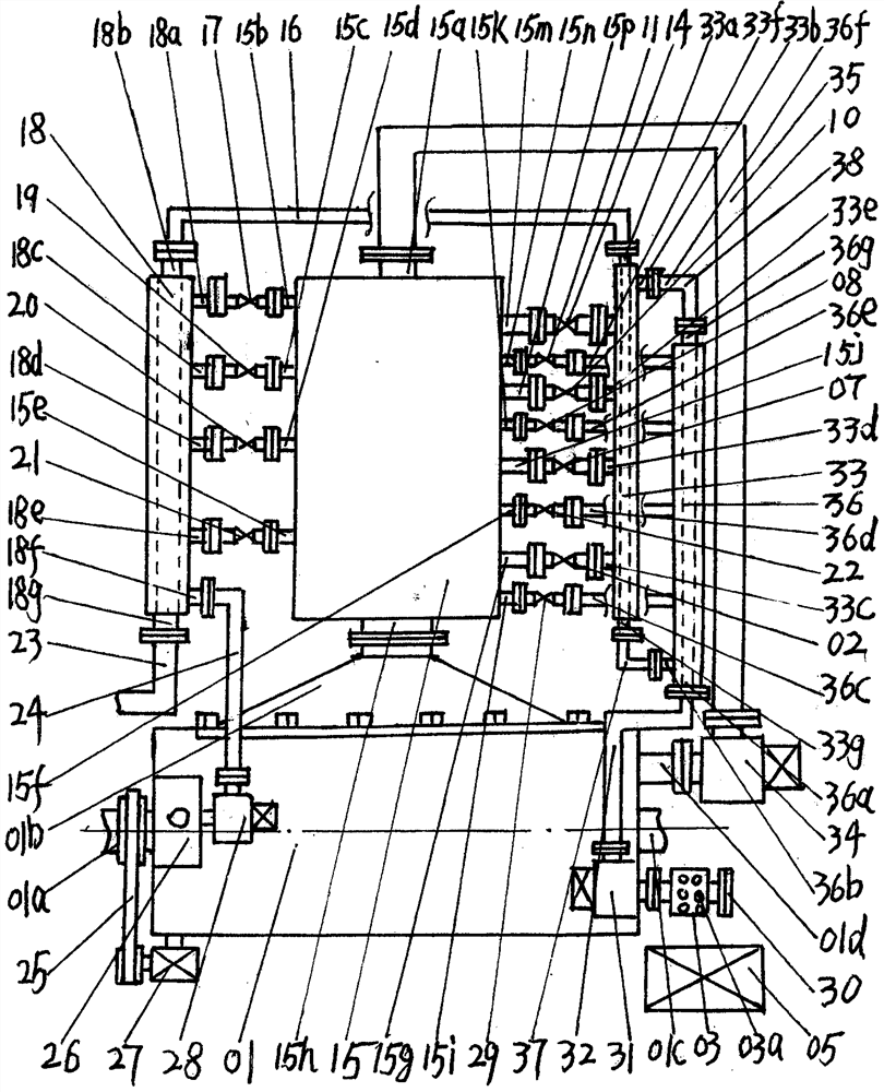
[0034] Such as figure 2 shown, with figure 1 The difference of Embodiment 1 is that: a supplementary supercharged electric air compressor 34 is fixed on the outlet flange interface 01d of the medium exhaust gas, and a simple return pipe 35 is fixed on the outlet of the supplementary supercharged electric air compressor 34 . The flange interface of the air outlet end of the simple return pipe 35 is fixedly connected with the inlet flange interface 15a of the working medium; the first exhaust gas regulating valve 11, the second exhaust gas regulating valve 08, the third exhaust gas regulating valve 22, the 4 The respective outlet ports of the waste gas regulating valve 29 are respectively connected to the flange interface 36f of the first branch heat exchange waste gas inflow, the second branch heat exchange waste gas flow into the flange interface 36e, the third branch heat exchange waste gas flow into the flange interface 36d, and the fourth branch The heat exchange waste ga...
Embodiment 2
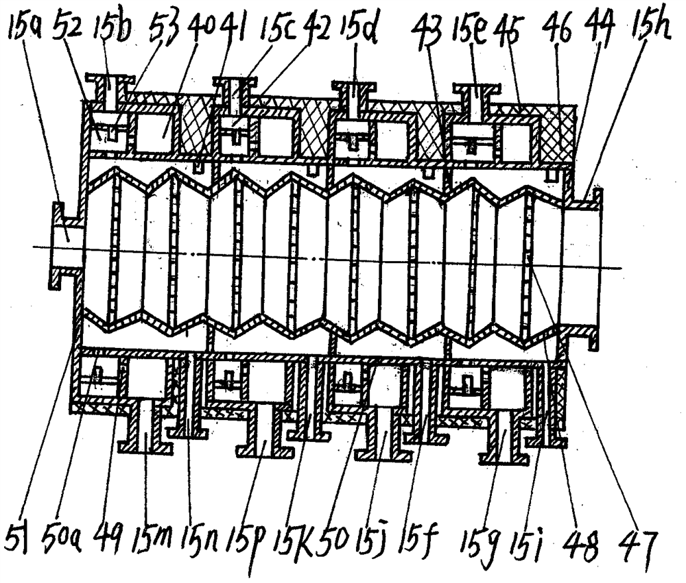
[0047] For embodiment two, the operation process different from embodiment one is: with reference to the attached figure 2 , image 3 , Figure 8 , the supplementary booster electric air compressor 34 after starting to work, the suction force formed by its inlet will further compress the medium air flowing out from the medium tail gas outlet flange interface 01d in the rotary jet machine 01 into a high-pressure air flow, and this high-pressure The air flows through the simple return pipe 35 and directly enters the multi-stage tubular burner 15 from the working medium inlet flange interface 15a to participate in heat transfer. After the fuel-air electric compressor 31 is turned on, the outside air enters the fuel-air electric compressor 31 from the air intake hole 03a and then enters the composite heat exchange tube 36 for exhaust gas collection through the air delivery pipe 32. 36, the air in the composite heat exchange inner tube 91 exchanges heat with the exhaust gas ente...
PUM
 Abstract
Description
Claims
Application Information
 - R&D
- Intellectual Property
- Life Sciences
- Materials
- Tech Scout
- Unparalleled Data Quality
- Higher Quality Content
- 60% Fewer Hallucinations
Browse by: Latest US Patents, China's latest patents, Technical Efficacy Thesaurus, Application Domain, Technology Topic, Popular Technical Reports.
© 2025 PatSnap. All rights reserved.Legal|Privacy policy|Modern Slavery Act Transparency Statement|Sitemap|About US| Contact US: help@patsnap.com


