A sensitivity measurement device and method applied to an ultra-wideband sampling receiver

A technology for measuring equipment and receivers, applied in receiver monitoring, radio wave measurement systems, instruments, etc., can solve problems such as high cost and implementation difficulty, poor versatility, etc., and achieve high promotion and application value, low cost, and improved measurement efficiency. Effect

Active Publication Date: 2021-09-28
BEIJING HONGDONG TECH CO LTD
View PDF8 Cites 0 Cited by
  • Summary
  • Abstract
  • Description
  • Claims
  • Application Information

AI Technical Summary

Problems solved by technology

[0007] Problems solved by the present invention: At present, the testing of ultra-wideband sampling receivers often requires the cooperation of multiple devices and self-developed modules to build a complex testing system, which has poor versatility, high cost and difficulty in implementation.

Method used


Image

  • A sensitivity measurement device and method applied to an ultra-wideband sampling receiver
  • A sensitivity measurement device and method applied to an ultra-wideband sampling receiver
  • A sensitivity measurement device and method applied to an ultra-wideband sampling receiver

Examples


Embodiment 1

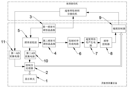
[0050] Such as figure 1 As shown, a sensitivity measurement device applied to ultra-wideband sampling receivers, including:

[0051] A display unit 1 for displaying measurement results and adjusting control equipment, the display unit 1 adopts a touch screen to realize human-computer interaction,

[0052] As the control and processor 2 of the equipment dispatching center, the control and processor 2 is implemented by a high-performance embedded processor, and the control and processor 2 is electrically connected to the display unit 1,

[0053] A first frequency adjustable constant temperature crystal oscillator 3 for generating a sliding sampling clock and transmitting it to the receiver under test,

[0054] A second frequency-adjustable constant temperature crystal oscillator 4 for generating a reference clock,

[0055] The first frequency adjustable constant temperature crystal oscillator 3 and the second frequency adjustable constant temperature crystal oscillator 4 both ...

Embodiment 2

[0079] This embodiment is a sensitivity measurement method applied to an ultra-wideband sampling receiver based on Embodiment 1, comprising the following steps:

[0080] S1, the second frequency controllable constant temperature crystal oscillator 4 generates a reference clock, and transmits the reference clock to the transmission timing forming circuit 6;

[0081] S2. The transmission timing forming circuit 6 shapes the reference clock into a transmission timing signal with a small duty ratio, drives the ultra-wideband signal generation circuit 7 of the subsequent stage to work, and generates the original ultra-wideband impulse pulse;

[0082] S3. The frequency band controller 8 performs band-limiting processing on the original ultra-wideband impulse pulse, so that the ultra-wideband impulse pulse meets the receiver test requirements in both the time domain and the frequency domain;

[0083] S4. The amplitude controller 9 performs attenuation control on the amplitude of the u...

Embodiment 3

[0090] This embodiment is a sensitivity measurement method applied to an ultra-wideband sampling receiver based on Embodiment 1, comprising the following steps:

[0091] S1, the second frequency controllable constant temperature crystal oscillator 4 generates a reference clock, and transmits the reference clock to the transmission timing forming circuit 6;

[0092] S2. The transmission timing forming circuit 6 shapes the reference clock into a transmission timing signal with a small duty ratio, drives the ultra-wideband signal generation circuit 7 of the subsequent stage to work, and generates the original ultra-wideband impulse pulse;

[0093] S3. The frequency band controller 8 performs band-limiting processing on the original ultra-wideband impulse pulse, so that the ultra-wideband impulse pulse meets the receiver test requirements in both the time domain and the frequency domain;

[0094] S4. The amplitude controller 9 performs attenuation control on the amplitude of the u...


PUM


Abstract

The invention provides a sensitivity measuring device and method applied to an ultra-wideband sampling receiver, wherein the device includes: a display unit, a control and a processor, a first frequency adjustable constant temperature crystal oscillator, a second frequency adjustable constant temperature crystal oscillator, a frequency difference Detection, emission timing formation circuit, ultra-wideband signal generation circuit, frequency band controller, amplitude controller, first AD acquisition circuit and second AD acquisition circuit, the method includes the following steps: S1, using a frequency-adjustable constant temperature crystal oscillator, respectively producing two S2, one of the square wave signals is directly transmitted to the receiver under test, and the other is used as a time reference, and is transmitted to the receiver under test after processing; S3, the receiver under test outputs an intermediate frequency signal, when the signal-to-noise ratio reaches 1 When :1, the amplitude of the currently injected UWB impulse pulse is the sensitivity value of the receiver under test. The invention solves the difficulty of measuring the sensitivity of the ultra-wideband sampling receiver, and has the advantages of simple operation and low cost.

Description

technical field [0001] The invention relates to the field of ultra-wideband (ultra-wideband) impulse system radar performance measurement, and specifically proposes a sensitivity measurement device and method applied to ultra-wideband sampling receivers. Background technique [0002] Sensitivity indicates the receiver's ability to receive weak signals, and it is an important technical indicator of radio equipment such as radars and detectors. The higher the sensitivity of the receiver, the weaker the signal it can receive, and the farther the radar's range will be. The sensitivity of a radar receiver is usually expressed in terms of the minimum detectable signal power, which is defined as: [0003] [0004] in k is the Boltzmann constant, T 0 is the absolute temperature, B 0 is the instantaneous bandwidth of the receiver, F 0 is the receiver noise figure, S 0 / N 0 The minimum signal-to-noise ratio required for signal identification at the receiver output. [00...

Claims


Application Information

Patent Timeline
Patent Type & Authority Patents(China)
IPC IPC(8): G01S7/40H04B17/29
CPCG01S7/4021H04B17/29
Inventor 吕波王全民贾立新冯建业任晓凯张延鹏何宏章
Owner BEIJING HONGDONG TECH CO LTD
Why Eureka
Try Eureka