Al technical title is built by PatSnap Al team. It summarizes the technical point description of the patent document.
A sub-pixel edge and detection method technology, applied in the field of image processing, to achieve the effect of improving efficiency, improving alignment efficiency, and facilitating fault detection
Pending Publication Date: 2021-07-16
CHINA COAL TECH & ENG GRP CHONGQING RES INST CO LTD
View PDF0 Cites 2 Cited by
Summary
Abstract
Description
Claims
Application Information
AI Technical Summary
This helps you quickly interpret patents by identifying the three key elements:
Problems solved by technology
Method used
Benefits of technology
Problems solved by technology
[0004] In order to solve the technical problem that the laser spot can be adaptively adjusted and the alignment accuracy of the marking circle is higher, the invention provides a sub-pixel edge detection method
Method used
Image
Click on the blue label to locate the original text in one second.
Reading with bidirectional positioning of images and text.
Examples
Embodiment 1
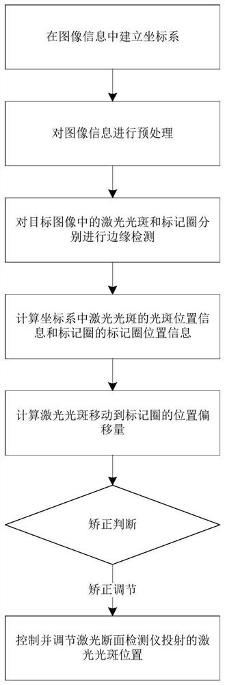
[0064] A sub-pixel edge detection method such as figure 1 shown, including the following steps:
[0065] The step of establishing a coordinate system is to establish a coordinate system in the collected image information, where the image information includes laser spots and marking circles. In this embodiment, the coordinate system is established with the lower right corner of the collected image information as the origin. In other embodiments, other points in the image information may also be used as the coordinate origin.
[0066] Image preprocessing is to perform image preprocessing on the image information to obtain the target image. In this embodiment, the image preprocessing is median filtering, which filters out impulse noise or granular noise, and protects image edges for subsequent edge detection.
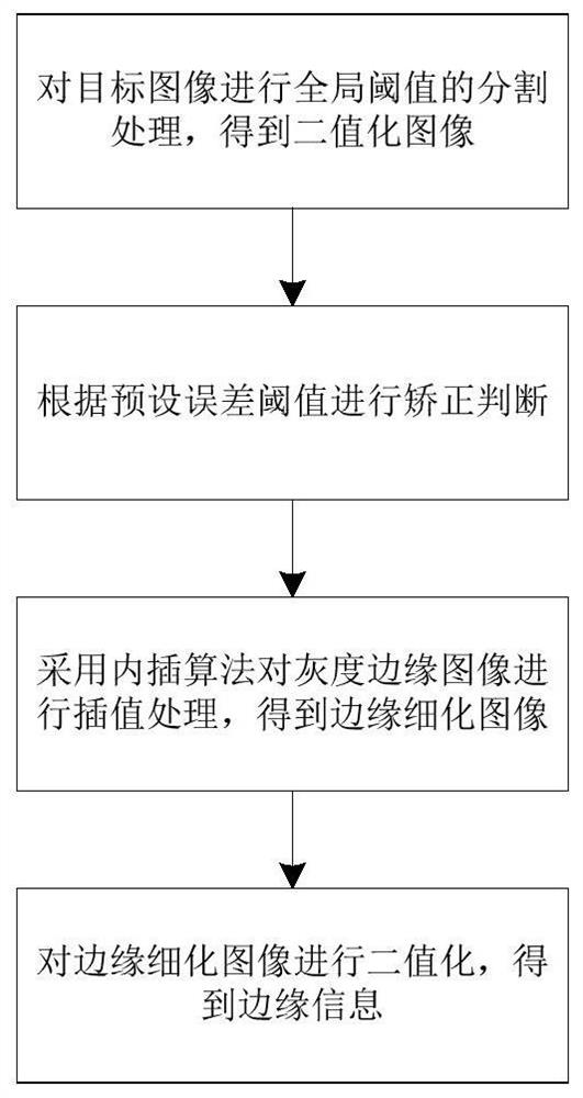
[0067] In the edge detection step, edge detection is performed on the laser spot and the marking circle in the target image respectively, to obtain the edge information o...
Embodiment 2
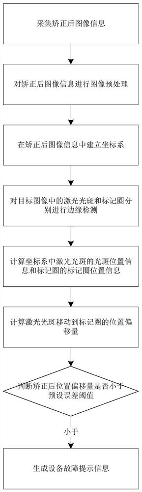
[0086] The difference from Embodiment 1 is that after the correction step, a correction effect tracking step is included to calculate the corrected position offset between the laser spot and the marking circle in the corrected image, and if the corrected position offset is less than the preset error If the threshold is not less than, a device failure prompt message is generated; if it is less than, an alignment completion prompt message is generated. Such as image 3 As shown, it specifically includes the following steps:
[0088] Step S2, establishing a coordinate system in the corrected image;
[0089] Step S3, performing image preprocessing on the corrected image information to obtain the corrected target image;
[0090] Step S4, performing edge detection on the laser spot and the marked circle in the corrected target image respectively, to obtain the edge information of the corrected light spot and the edge infor...
PUM
Abstract
The invention relates to the technical field of image processing, and particularly discloses a sub-pixel edge detection method, which comprises the following steps: a coordinate system establishment step: establishing a coordinate system in collected image information; image preprocessing: performing image preprocessing on the image information to obtain a target image; an edge detection step: respectively carrying out edge detection on the laser spot and the marking ring in the target image to obtain spot edge information and marking ring edge information; a position calculation step: respectively calculating light spot position information of the laser light spot and marking ring position information of the marking ring in the coordinate system according to the light spot edge information and the marking ring edge information; an offset calculation step: calculating the position offset of the laser spot moving to the marking ring according to the spot position information and the marking ring position information; and a correction step: controlling and adjusting the position of the laser spot projected by the laser section detector according to the position offset. By adopting the technical scheme of the invention, the alignment precision of the laser spot and the marking ring is higher.
Description
technical field [0001] The invention relates to the technical field of image processing, in particular to a sub-pixel edge detection method. Background technique [0002] Tunnel refers to an underground engineering structure excavated in rock and soil to form an underground passage. Due to our country's geographical factors, urban development, and traffic development, tunnel engineering has great potential for development. Among them, the tunnel section measurement in the early stage of the tunnel project is a survey project that must be carried out during the tunnel construction and the completion acceptance stage. It controls the plane, elevation and section geometry of the tunnel excavation, and is related to whether the tunnel can be excavated. [0003] At present, tunnel section detection is often processed by total station, laser profiler and background data processing system. Due to the use of non-cooperative target laser ranging technology and precise angle measurem...
Claims
Application Information
Patent Timeline
Application Date:The date an application was filed.
Publication Date:The date a patent or application was officially published.
First Publication Date:The earliest publication date of a patent with the same application number.
Issue Date:Publication date of the patent grant document.
PCT Entry Date:The Entry date of PCT National Phase.
Estimated Expiry Date:The statutory expiry date of a patent right according to the Patent Law, and it is the longest term of protection that the patent right can achieve without the termination of the patent right due to other reasons(Term extension factor has been taken into account ).
Invalid Date:Actual expiry date is based on effective date or publication date of legal transaction data of invalid patent.