Supercharge Your Innovation With Domain-Expert AI Agents!

End effector of oral implant robot and compliance control method

An end-effector and robot technology, which is used in dental implants, medical science, dentistry, etc., can solve the problems of uneven force on the drill needle, axis offset, joint rotation position error, cavity accuracy, etc., so as to improve the cavity accuracy. , the effect of avoiding errors and reducing stiffness requirements

Pending Publication Date: 2021-07-23
ZHEJIANG UNIV OF TECH
View PDF0 Cites 0 Cited by
  • Summary
  • Abstract
  • Description
  • Claims
  • Application Information

AI Technical Summary

Problems solved by technology

[0007] In order to overcome the shortcomings of the existing technology, in order to ensure the accuracy of the axial feed movement along the cavity, make the overall rigidity of the robot meet the stability requirements of the end pose, solve the impact of the superposition of the joint rotation position error of the oral implant robot on the cavity accuracy, and solve the problem of The axis deviation problem caused by its non-uniform mechanical characteristics when drilling holes in the jaw further improves the accuracy of oral implant robot surgery. The end effector and compliance control method of the dental implant robot provide a redundant degree of freedom for the dental implant robot and use the axis compliance control to adapt to the uneven force on the drill needle due to its non-uniform mechanical characteristics when preparing a cavity in the jaw and axis offset issues

Method used


Image

  • End effector of oral implant robot and compliance control method
  • End effector of oral implant robot and compliance control method
  • End effector of oral implant robot and compliance control method

Examples


Embodiment Construction

[0039] The present invention will be further described below in conjunction with the accompanying drawings.

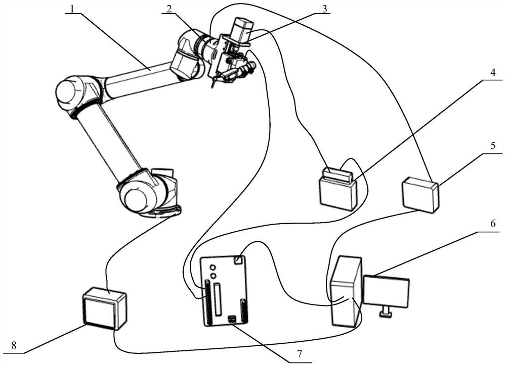
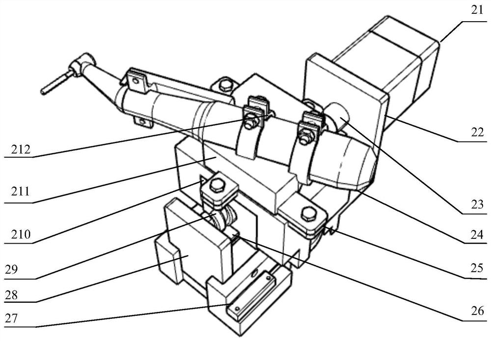
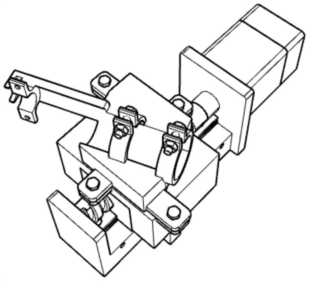
[0040] refer to Figure 1 ~ Figure 4 , an end effector of an oral implant robot, comprising a six-dimensional force sensor 2, a linear feed mechanism, a closed-loop stepper motor driver 4 and a linear displacement sensor 28, the linear feed mechanism comprising a closed-loop stepper motor 21, a ball screw 29 , the slider 210 and the planting mobile phone 24, the closed-loop stepper motor 21 is connected with the ball screw 210 through a coupling, the slider 210 is installed on the ball screw 29, the clamping mechanism 211 is connected with the slider 210 through bolts, and the clamping The mechanism 211 clamps the planting mobile phone 24, and a rubber pad 212 is installed between the two to increase friction and shock absorption; during the feeding process, the output shaft of the closed-loop stepping motor 22 rotates, which is converted into linear displacement by th...


PUM


Abstract

An end effector of an oral implant robot comprises a six-dimensional force sensor, a linear feeding mechanism, a closed-loop stepping motor driver and a linear displacement sensor, in the linear feeding mechanism, the closed-loop stepping motor is connected with a ball screw through a coupler, a sliding block is installed on the ball screw, a clamping mechanism is connected with the sliding block through a bolt, a clamping mechanism clamps a planting mobile phone, and a rubber pad is mounted between the clamping mechanism and the planting mobile phone. In the feeding process, an output shaft of the stepping motor rotates, rotation is converted into linear displacement through the ball screw to drive the sliding block to move, the sliding block drives the clamping mechanism and the planting mobile phone to move, a linear displacement sensor is installed on the side of the linear feeding mechanism, and one end of the sensor abuts against the sliding block to measure the relative distance between the sliding block and the sensor. The sliding block and the sensor are integrally installed above a flange, and the flange is connected to the six-dimensional force sensor. The invention also provides a compliance control method of the oral implant robot. The caving precision is improved, and the robot can move more flexibly.

Description

technical field [0001] The invention relates to the technical field of oral implant robots, in particular to an end effector for an oral implant robot that feeds with a single degree of freedom along the axial direction of an implant cavity and a compliance control method thereof. Background technique [0002] The loss of teeth will affect people's chewing, pronunciation, appearance and digestion functions, seriously reducing the quality of life of patients, and implant restoration is an important means of repairing tooth loss, known as the "first human" after deciduous teeth and permanent teeth Three teeth". [0003] Dental implant refers to a method of restoring missing teeth based on the lower structure (implant) implanted in bone tissue to support and retain the upper tooth restoration. It uses artificial materials (such as metal, ceramics, etc.) to make implants (generally similar to the shape of tooth roots), which are surgically implanted into tissues (usually the up...

Claims


Application Information

Patent Timeline
IPC IPC(8): A61C8/00
CPCA61C8/00A61C8/0089
Inventor 刘云峰周翔宇阚天舒
Owner ZHEJIANG UNIV OF TECH
Features
  • R&D
  • Intellectual Property
  • Life Sciences
  • Materials
  • Tech Scout
  • Unparalleled Data Quality
  • Higher Quality Content
  • 60% Fewer Hallucinations
Learn More