Supercharge Your Innovation With Domain-Expert AI Agents!

Core pulling system and core pulling method applied to die-casting molds

A die-casting die and core-pulling needle technology, applied in the die-casting die field, can solve the problems of complex die-casting die structure, inability to adapt, and large die-casting die structure, achieve complex structural arrangement in a small space, ensure the molding yield, overcome the The effect of over-tightening

Pending Publication Date: 2021-07-23
宁波臻至机械制造有限公司
View PDF10 Cites 6 Cited by
  • Summary
  • Abstract
  • Description
  • Claims
  • Application Information

AI Technical Summary

Problems solved by technology

For some auto parts with complex structures, the corresponding die-casting mold structure is also very complicated, especially for those products with more side holes and undercuts, the core-pulling system required by the corresponding die-casting molds is also more complicated
[0003] In the core-pulling system of some existing die-casting molds, due to the complexity of the product, the large slider, and the large tightening force of the product on the slider, it is easy to strain the product or cause product deformation during core-pulling; on the other hand, for some machine tonnages Limited manufacturers, complex core-pulling system, if the layout is unreasonable, the structure of the die-casting mold will be too large, and then it is necessary to use a large-tonnage die-casting machine to adapt to this type of die-casting mold, or even unable to adapt Correspondingly, if a large-tonnage machine is used to form a product, the unit forming cost of the product will increase a lot

Method used


Image

  • Core pulling system and core pulling method applied to die-casting molds
  • Core pulling system and core pulling method applied to die-casting molds
  • Core pulling system and core pulling method applied to die-casting molds

Examples


Embodiment Construction

[0047] The following are specific embodiments of the present invention and in conjunction with the accompanying drawings, the technical solutions of the present invention are further described, but the present invention is not limited to these embodiments.

[0048]It should be noted that all directional indications (such as up, down, left, right, front, back...) in the embodiments of the present invention are only used to explain the relationship between the components in a certain posture (as shown in the accompanying drawings). Relative positional relationship, movement conditions, etc., if the specific posture changes, the directional indication will also change accordingly.

[0049] In addition, in the present invention, descriptions such as "first", "second", "one" and so on are used for descriptive purposes only, and should not be understood as indicating or implying their relative importance or implicitly indicating the indicated technical features quantity. Thus, the ...


PUM


Abstract

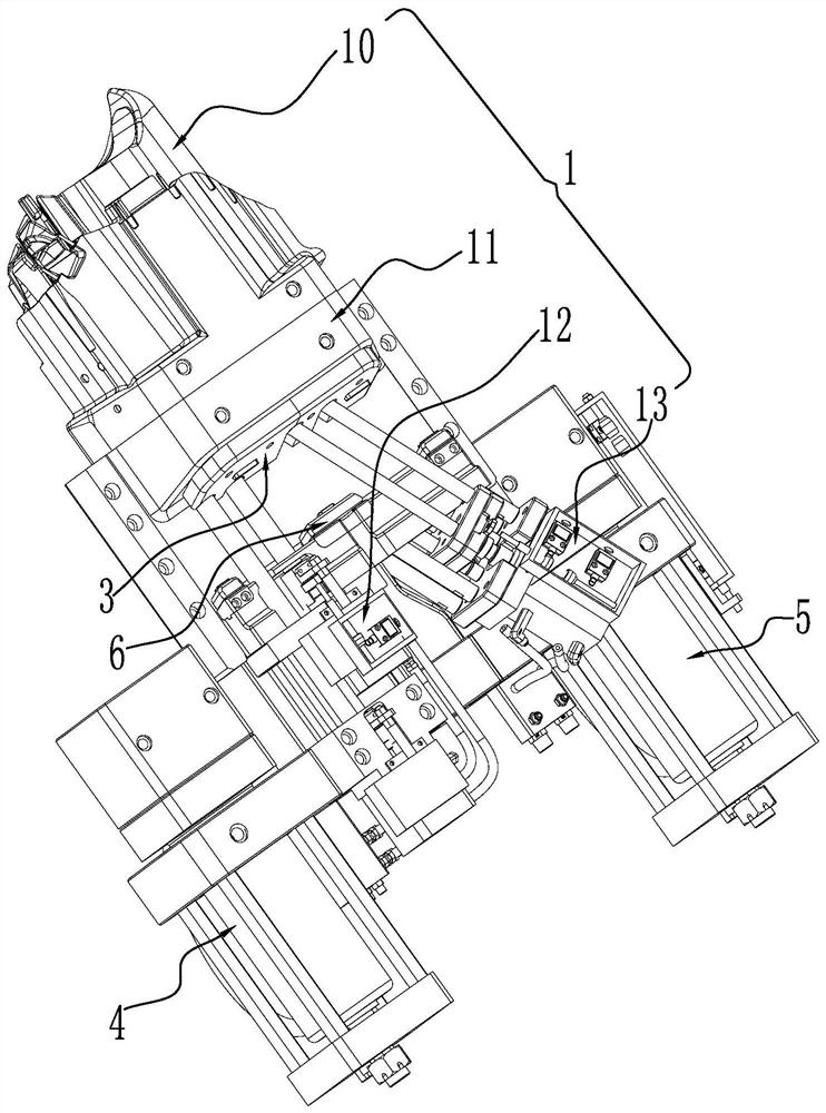
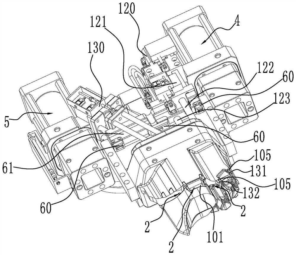
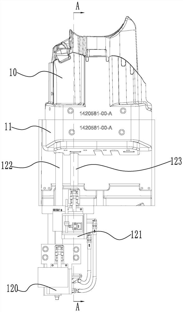
The invention relates to the technical field of die-casting molds and discloses a core pulling system and a core pulling method applied to die-casting molds. A die-casting mold comprises a movable mold and a fixed mold. The core pulling system comprises a sliding block assembly, ejector pins, a pressing plate, a first driving oil cylinder and a second driving oil cylinder, wherein the sliding block assembly comprises a sliding block, a sliding seat, an extrusion mechanism and a pin pulling mechanism; the extrusion mechanism and the pin pulling mechanism are arranged on the sliding seat; the front part of the sliding block is provided with a molded surface attached to a product; ejector pin holes are formed in the sliding block and the sliding seat; the ejector pins are arranged in the ejector pin holes in a penetrating manner and are sleeved with elastic parts; the pressing plate is movably arranged on the sliding seat; the pressing plate is provided with a straight surface and an inclined surface against which the ejector pins abut; one end, away from the sliding block, of each ejector pin movably abuts against the straight surface or the inclined surface; the abutting positions of the ejector pins can be switched between the straight surface and the inclined surface; and the first driving oil cylinder and the second driving oil cylinder are used for synchronously driving the sliding block assembly. The core pulling system has the advantages of compact structure, high stability is high and low rejection rate of formed products.

Description

technical field [0001] The invention relates to the technical field of die-casting molds, in particular to a core-pulling system and a core-pulling method for a die-casting mold. Background technique [0002] Many automobile parts, especially aluminum alloy parts, are formed by die-casting molds. For some auto parts with complex structures, the corresponding die-casting mold structure is also very complicated, especially for those products with more side holes and undercuts, the core-pulling system required by the corresponding die-casting molds is also more complicated. [0003] In the core-pulling system of some existing die-casting molds, due to the complexity of the product, the large slider, and the large tightening force of the product on the slider, it is easy to strain the product or cause product deformation during core-pulling; on the other hand, for some machine tonnages Limited manufacturers, complex core-pulling system, if the layout is unreasonable, the struct...

Claims


Application Information

Patent Timeline
IPC IPC(8): B22D17/22B22D17/24
CPCB22D17/22B22D17/24
Inventor 唐卫平张群峰罗礼斌周金荣徐挺
Owner 宁波臻至机械制造有限公司
Features
  • R&D
  • Intellectual Property
  • Life Sciences
  • Materials
  • Tech Scout
  • Unparalleled Data Quality
  • Higher Quality Content
  • 60% Fewer Hallucinations
Learn More