
Pre-combustion chamber device for improving combustion and reducing thermal loads and engine

A technology of pre-combustion chamber and heat load, which is applied in the direction of combustion engine, internal combustion piston engine, fuel heat treatment device, etc., can solve the problems of large ignition, instability, poor combustion stability of the main combustion chamber, etc., and achieve the reduction of residual exhaust gas coefficient, Effects of improving combustion, reducing heat load, and improving combustion stability

Pending Publication Date: 2021-07-23
东莞市晨兴智能精密装备有限公司
View PDF0 Cites 2 Cited by
  • Summary
  • Abstract
  • Description
  • Claims
  • Application Information

AI Technical Summary

Problems solved by technology

[0006] The technical problem to be solved by the present invention is: in the prior art, the residual exhaust gas coefficient in the pre-combustion chamber is relatively large and the ignition instability of the pre-combustion chamber under low temperature environment causes the combustion stability of the main combustion chamber to be poor and the injection hole of the pre-combustion chamber The thermal load of the nearby pre-chamber body is too high, providing a pre-chamber device and engine that improves combustion and reduces thermal load

Method used


Image

  • Pre-combustion chamber device for improving combustion and reducing thermal loads and engine
  • Pre-combustion chamber device for improving combustion and reducing thermal loads and engine

Examples


Embodiment Construction

[0033] In order to make the technical problems, technical solutions and beneficial effects solved by the present invention clearer, the present invention will be further described in detail below in conjunction with the accompanying drawings and embodiments. It should be understood that the specific embodiments described here are only used to explain the present invention, not to limit the present invention.

[0034] It should be noted that the orientation terms such as up, down, inside, outside, top, and bottom in the following text are only relative concepts or refer to the normal use status of the product, and should not be regarded as restrictive .

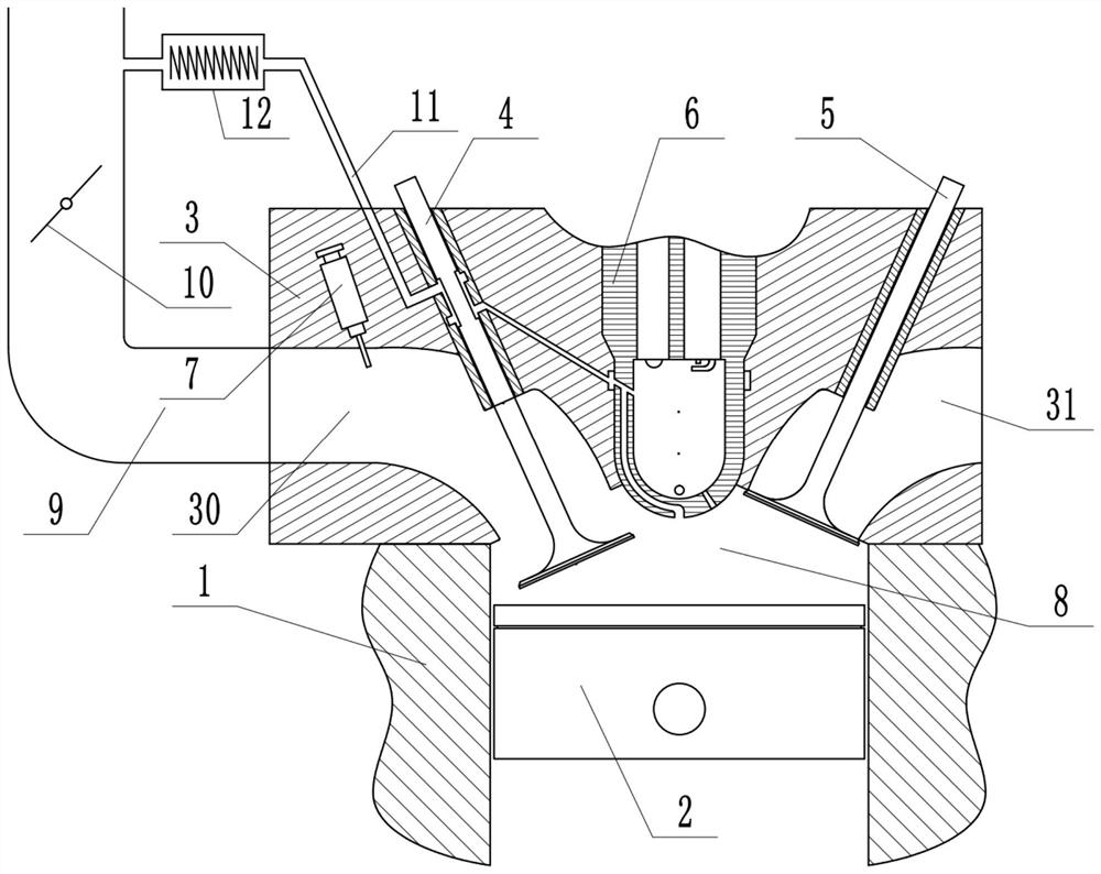
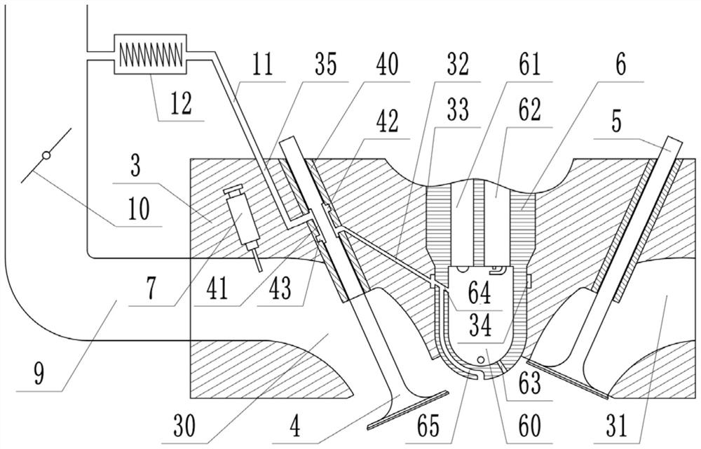
[0035] Such as Figure 1-2 As shown, the pre-chamber device for improving combustion and reducing heat load provided by an embodiment of the present invention includes cylinder head 3, intake valve 4, intake valve guide 40, intake pipe 9, pre-chamber body 6 and gas connection Pipe 11, the cylinder head 3 is provided with a p...


PUM


Abstract

The invention relates to a pre-combustion chamber device capable of improving combustion and reducing thermal loads and an engine. The pre-combustion chamber device comprises a cylinder cover, an intake valve, an intake valve guide pipe, an intake pipe, a pre-combustion chamber body, a gas connecting pipe and a heater. A pre-combustion chamber inner cavity is formed in the pre-combustion chamber body, and the cylinder cover is provided with an intake channel, a cylinder cover air entraining channel and a cylinder cover gas channel. The outer end of the intake channel is communicated with the intake pipe, the gas connecting pipe is connected between the intake pipe and an inlet of the cylinder cover air entraining channel, the heater is connected to the middle of the gas connecting pipe, and the pre-combustion chamber body is provided with a pre-combustion chamber scavenging channel communicated with an outlet of the cylinder cover gas channel and the pre-combustion chamber inner cavity. A pre-combustion chamber cooling channel with the upper end being communicated with the middle of the pre-combustion chamber scavenging channel, and the lower end being communicated with a main combustion chamber of the engine is further formed in the pre-combustion chamber body. According to the pre-combustion chamber device for improving combustion and reducing the thermal loads, the combustion stability of the main combustion chamber of the engine can be improved, and meanwhile the thermal loads of the pre-combustion chamber body can be reduced.

Description

technical field [0001] The invention belongs to the technical field of automobile engines, in particular to a pre-combustion chamber device and an engine for improving combustion and reducing heat load. Background technique [0002] As fuel consumption regulations become more stringent, ultra-high thermal efficiency of internal combustion engines has become the goal pursued. Accelerating the combustion speed, increasing the isovolume, reducing heat loss, and suppressing knocking are effective means to improve the thermal power conversion efficiency of gasoline engines. The pre-chamber jet ignition technology can increase the combustion speed, suppress knocking, and extend the lean burn limit, and has certain potential in improving the thermal efficiency of gasoline engines. The jet ignition of the pre-combustion chamber first ignites the mixed gas in the cavity of the pre-chamber, and the high-temperature and high-pressure mixed gas is sprayed to the main combustion chamber...

Claims


Application Information

Patent Timeline
IPC IPC(8): F02B19/10F02B19/16F02B19/18F02B25/02F02M31/13F02N19/04F01P1/06F02F1/24F02F1/42F02M61/14F01L3/08F01L3/20
CPCF01L3/08F01L3/20F01P1/06F02B19/1009F02B19/1028F02B19/1033F02B19/1042F02B19/108F02B19/16F02B19/18F02B25/02F02B2019/004F02F1/24F02F1/4235F02M31/13F02M61/14F02M61/145F02N19/04Y02T10/12
Inventor 郭丽军王建安黄玉婷刘曦光晏润开
Owner 东莞市晨兴智能精密装备有限公司
Learn More