Fuel saving joint and fuel economizer

A technology of body and magnetic sheet, applied in machine/engine, internal combustion piston engine, engine components, etc., can solve the problems of inability to intercept large particles of impurities, inconspicuous magnetic force line aggregation, low fuel efficiency improvement, etc., to reduce the diameter of oil droplets, The effect of improving the degree of aggregation and improving the magnetization efficiency

Pending Publication Date: 2021-07-23
朱小琴
View PDF0 Cites 1 Cited by
  • Summary
  • Abstract
  • Description
  • Claims
  • Application Information

AI Technical Summary

Problems solved by technology

[0005] No filter element, unable to intercept large particles of impurities, the magnetic field lines are not obvious, and the fuel efficiency is not improved

Method used


Image

  • Fuel saving joint and fuel economizer
  • Fuel saving joint and fuel economizer
  • Fuel saving joint and fuel economizer

Examples


Embodiment 1

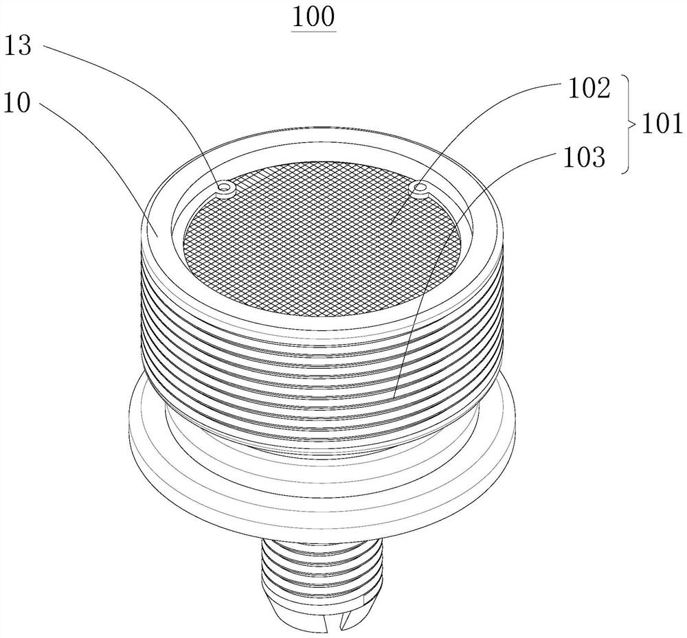
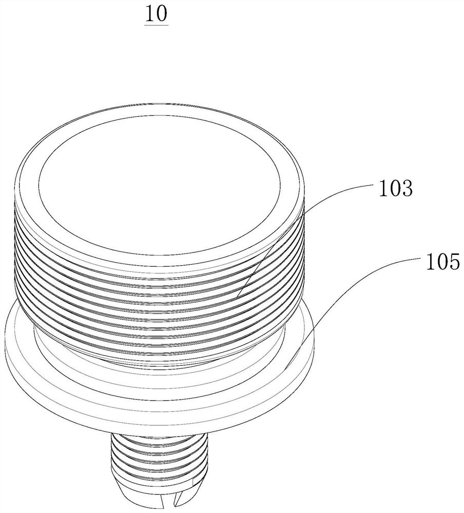
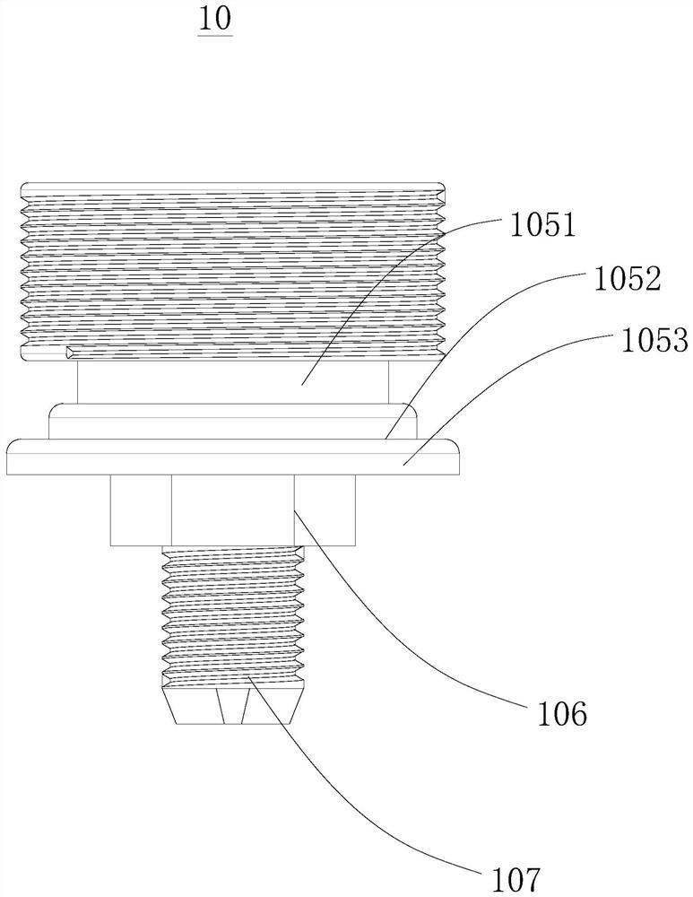
[0051] Please refer to figure 1 , figure 1 An explosion schematic diagram of the fuel-saving joint 100 provided by the embodiment of the present invention. The fuel-saving joint 100 includes a joint body 10 , a magnetic plate assembly 11 and a filter screen assembly 12 . The joint body 10 has an accommodating chamber 101 , the filter screen assembly 12 is embedded in the accommodating chamber 101 , and partitions the accommodating chamber 101 to form a first accommodating chamber 102 and a second accommodating chamber 103 . The magnetic chip assembly 11 includes a magnetic chip body 111 and a sandwich layer 112. The sandwich layer 112 is arranged in the second accommodation cavity 103, and cooperates with the second accommodation cavity 103 to form a magnetic chip housing for accommodating the magnetic chip body 111. cavity, the magnetic chip body 111 is embedded in the magnetic chip accommodating cavity. Both the magnetic sheet body 111 and the sandwich layer 112 have notc...

Embodiment 2

[0074] This embodiment provides a fuel-saving device, which includes the fuel-saving joint 100 and the fuel-saving tube in Embodiment 1, and the fuel-saving joint 100 and the fuel-saving tube are connected to each other. It has all the advantages of the fuel-efficient street.

[0075] Effect example

[0076] In the actual use process, according to the inspection report of motor vehicle exhaust pollution in Taizhou City, the car using the fuel economizer (purchased on June 1, 2003), the current mileage: 182797 (km), in September 2020 After installing the fuel saver on the 13th, it is practical for commuting to and from get off work every day. On January 9, 2021, I went to Taizhou Vehicle Inspection Center for testing. The following is the report obtained by the inspection center:

[0077] Hydrocarbon (HC) measured value: 0.01, less than the national limit of 1.6 (g / km);

[0078] The measured value of carbon monoxide (CO): 0.78, which is less than the national limit of 8.0 (g / k...


PUM


Abstract

The invention provides a fuel saving joint and a fuel economizer, and relates to the technical field of automobile fuel saving. The oil saving joint comprises a joint body, a magnetic sheet assembly, and a filter screen assembly. The joint body is provided with a containing cavity; and the filter screen assembly is embedded in the containing cavity and divides the containing cavity into a first containing cavity and a second containing cavity. The magnetic sheet assembly comprises a magnetic sheet body and a clamping body layer; the clamping body layer is arranged in the second containing cavity and matched with the second containing cavity to form a magnetic sheet containing cavity for containing the magnetic sheet body; and the magnetic sheet body is embedded in the magnetic sheet containing cavity. The magnetic sheet body and the clamping body layer are both provided with notches, and the notches correspond to each other and are matched with each other. According to the oil saving joint, the magnetic sheet assembly and a filtering assembly are arranged in the containing cavity, and fuel is filtered and magnetized, so that the diameter of fuel drops is reduced, the fuel efficiency is improved, flue gas emission is reduced, and the effects of energy conservation and emission reduction are achieved. The fuel economizer comprises the fuel saving joint, and has all the beneficial effects of the fuel saving joint.

Description

technical field [0001] The invention relates to the technical field of automobile fuel saving, in particular to a fuel saving joint and a fuel saving device. Background technique [0002] Fuel-saving devices can be roughly divided into three categories: additives, fuel-saving devices, and fuel-saving stickers. The main fuel-saving principle is to improve the performance of the engine by decomposing and cleaning the dissolved colloid and other various deposited impurities in the fuel pipeline of the carburetor and the injection system, thereby improving fuel efficiency and reducing fuel consumption. [0003] Most of the existing fuel economizers include a fuel saving joint, and a magnetic piece is installed inside the fuel saving joint to magnetize the fuel molecules, thereby reducing the viscosity and density of the fuel molecules, making the oil droplets smaller, which is beneficial to the physical and chemical properties of the fuel. Combustion, reduce the blackness of ex...

Claims


Application Information

Patent Timeline
Patent Type & Authority Applications(China)
IPC IPC(8): F02M27/04F02M37/34F02M37/42
CPCF02M27/04F02M37/34F02M37/42Y02T10/12
Inventor 朱小琴
Owner 朱小琴
Why Eureka
Try Eureka