Low Hydraulic Swirl Ejector

A technology of injector and low hydraulic pressure, which is applied in the direction of fuel injection devices, machines/engines, mechanical equipment, etc. It can solve the problems of unsatisfactory atomization particle size of injectors, poor assembly process, and inability to contact and mix with air.

Active Publication Date: 2022-02-25
NANYUE FUEL INJECTION SYST CO LTD
View PDF10 Cites 0 Cited by
  • Summary
  • Abstract
  • Description
  • Claims
  • Application Information

AI Technical Summary

Problems solved by technology

The existing general injector, under the low hydraulic pressure of 3bar to 10Bar, the atomization particle size of the injector is not ideal, the flow consistency is poor, and it cannot fully contact and mix with the air, thus affecting the emission performance of the vehicle
Moreover, the structure is complex, the assembly process is poor, and the cost is high

Method used


Image

  • Low Hydraulic Swirl Ejector
  • Low Hydraulic Swirl Ejector
  • Low Hydraulic Swirl Ejector

Examples


Embodiment Construction

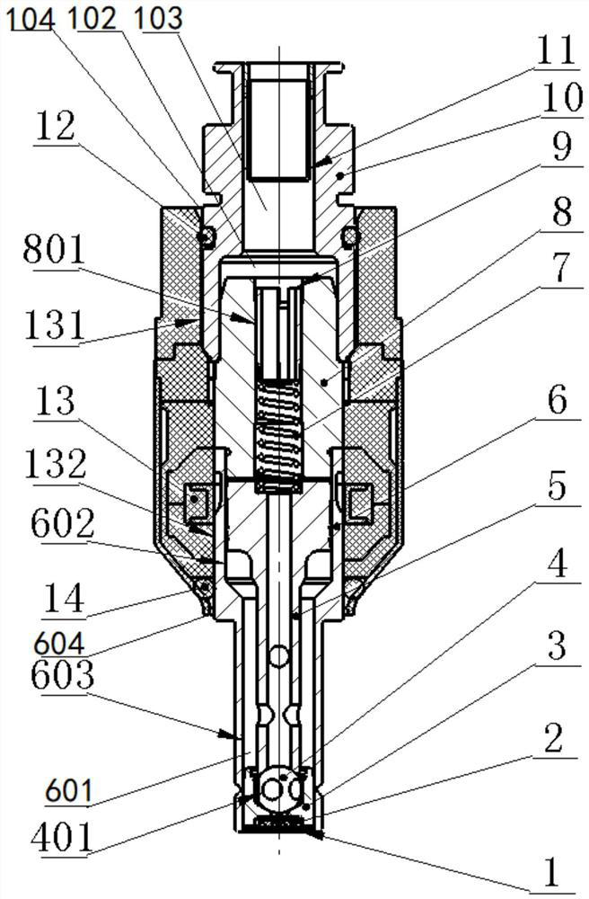
[0024] Structure of the present invention, further concrete description is as follows in conjunction with accompanying drawing:

[0025] see Figure 1 to Figure 7 , the low hydraulic swirl injector given in the figure mainly includes the electromagnet part 13, the oil inlet joint, the iron core spring assembly and the injection valve assembly. The oil inlet joint includes a filter screen support 10 , a filter screen 11 and an O-ring seal 12 . A middle hole 103 is arranged in the filter screen support 10 , and the filter screen 11 is placed in the middle hole 103 .

[0026] The iron core spring assembly includes an iron core 8 , a spring upper seat 9 and a spring 7 .

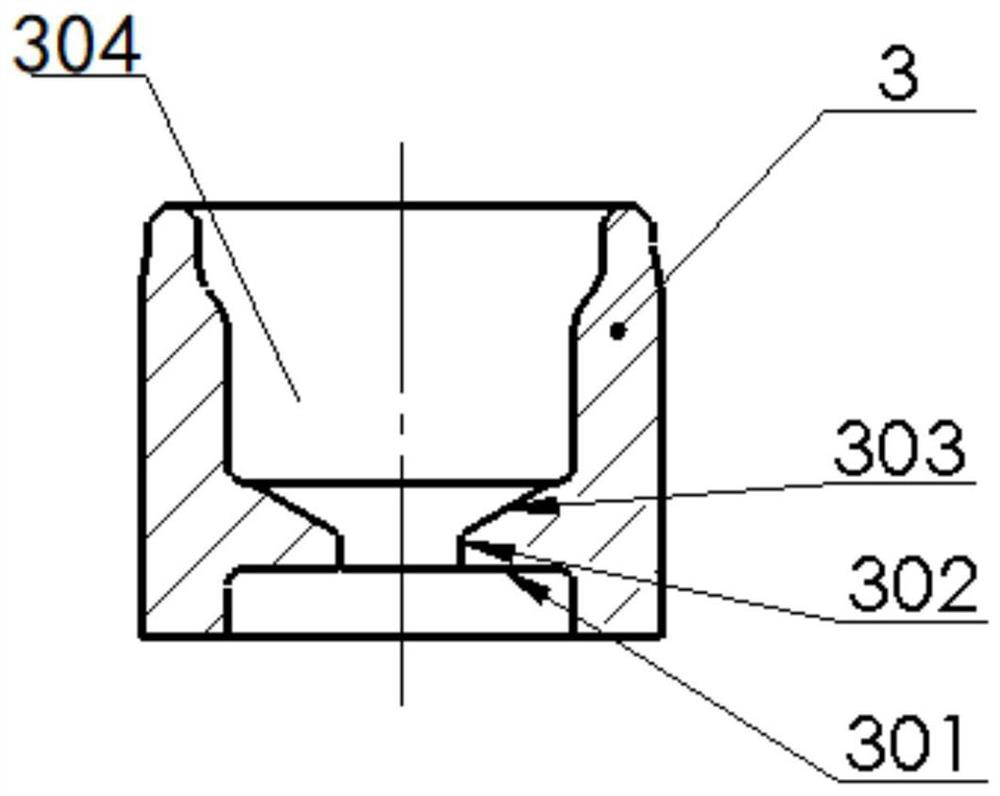
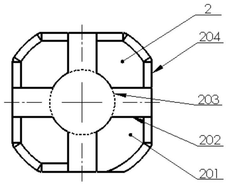
[0027] The injection valve assembly includes a nozzle body 6 , a valve stem 5 , a steel ball 4 , a valve seat 3 , a swirl plate 2 and a nozzle plate 1 .

[0028] The valve seat 3 is fixed at the lower end of the inner hole 603 of the nozzle body 6 by laser welding. See especially figure 2 , The valve seat 3...


PUM


Abstract

The invention discloses a low-hydraulic swirl injector, which comprises an electromagnet part, an oil inlet joint, an iron core spring assembly and an injection valve assembly installed in the electromagnet part sequentially from top to bottom; wherein, the swirl plate The upper surface of the swirl plate is provided with diversion sinkholes and several diverter grooves, the outer circle of the swirl plate is provided with flat squares corresponding to the diverter grooves, and the lower surface of the swirl plate is provided with swirl holes and several swirl grooves. After the fluid passes through the swirl groove, it will produce violent impact and form turbulent flow and converge into the swirl hole. The particle size of the atomized particles will be significantly increased. There are nozzle holes on the nozzle plate for precise control of the injection flow. The invention has the advantages of being able to improve the particle size of atomized particles, improving flow consistency, simple and reasonable structure, convenient manufacture and assembly, and low production cost.

Description

technical field [0001] The invention relates to the technical field of auto parts manufacturing, in particular to a low-hydraulic swirl injector. Background technique [0002] At present, injectors with low hydraulic pressure of 3bar to 10bar are more and more widely used. Under the control of the electronic control unit, the injector atomizes a certain amount of fuel and sprays it into the intake port or exhaust pipe to mix with air. According to the different types of injected fuel, injectors can be divided into gasoline injectors, methanol injectors, urea injectors, etc. [0003] With the gradual improvement of emission requirements, the requirements for the atomized particle size of the injector are getting higher and higher. Existing general injectors have unsatisfactory atomization particle size and poor flow consistency under the low hydraulic pressure of 3bar to 10Bar, and cannot fully contact and mix with air, thereby affecting the emission performance of the vehic...

Claims


Application Information

Patent Timeline
Patent Type & Authority Patents(China)
IPC IPC(8): F02M51/06F02M61/10F02M61/18F01N3/36
CPCF02M51/061F02M61/10F02M61/1886F02M61/1853F02M61/188F02M61/1893F01N3/36F01N2610/1453Y02T10/12
Inventor 欧阳玲湘李成校朱宏志贾昭远龙美彪黄民备邓飞
Owner NANYUE FUEL INJECTION SYST CO LTD
Why Eureka
Try Eureka