Bearing rolling body rolling friction force measuring system and loading device thereof

A technology of rolling friction force and loading device, which is applied in the direction of measuring device, mechanical bearing test, and mechanical device, etc. It can solve the problems of inability to accurately measure the rolling friction force of rolling elements and the inability to accurately evaluate the friction and wear performance of rolling elements

Active Publication Date: 2021-07-23
HENAN UNIV OF SCI & TECH
View PDF3 Cites 2 Cited by
  • Summary
  • Abstract
  • Description
  • Claims
  • Application Information

AI Technical Summary

Problems solved by technology

[0004] However, when testing the entire rolling bearing, the bearing ring is mostly loaded. At this time, the force on the rolling element is complicated, and factors such as the bearing cage, end cover, and assembly preload will affect the rolling friction between the rolling element and the inner and outer rings. Force, the system factors in the bearing will lead to the inability to accurately measure the rolling friction of the rolling element, and it is also impossible to accurately evaluate the friction and wear properties of the rolling element. Therefore, it is necessary to develop a friction measurement system in order to avoid Bearing system factor interference

Method used


Image

  • Bearing rolling body rolling friction force measuring system and loading device thereof
  • Bearing rolling body rolling friction force measuring system and loading device thereof
  • Bearing rolling body rolling friction force measuring system and loading device thereof

Examples


specific Embodiment 1

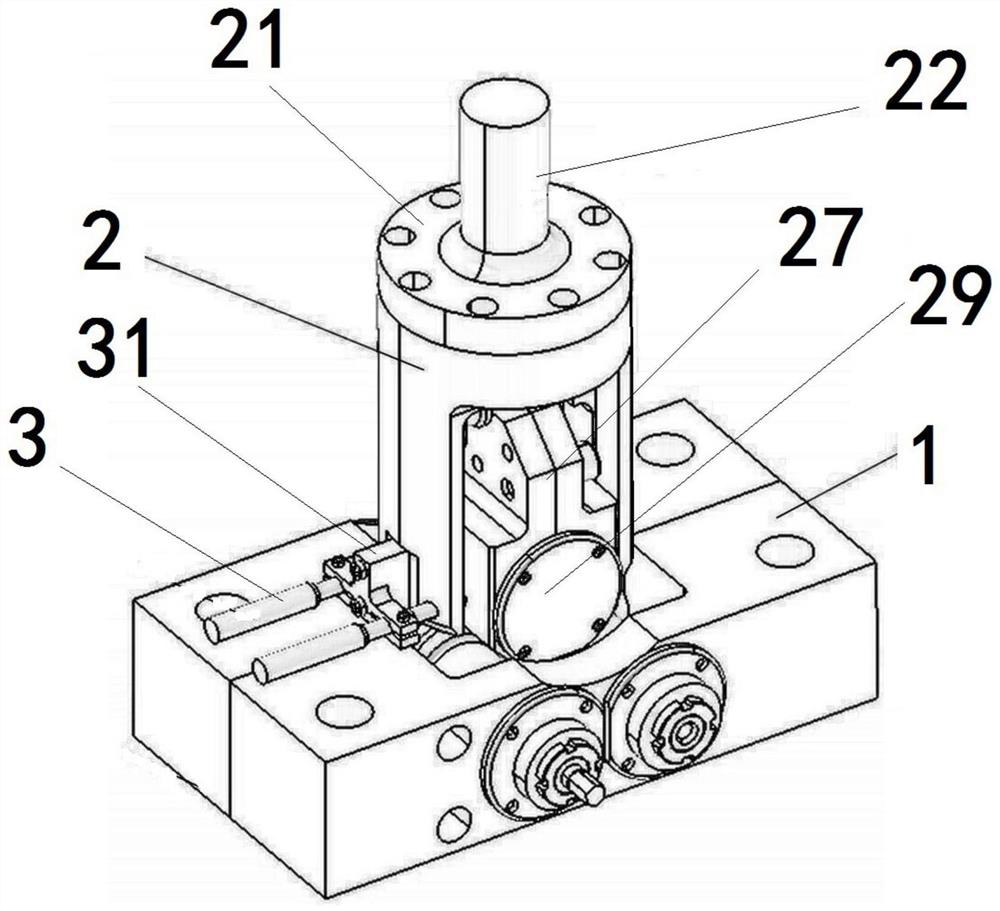
[0079] In the prior art, when measuring the rolling friction force between the rolling element and the inner and outer rings in the rolling bearing, it is often to carry out experimental research on the entire rolling bearing under different rotational speeds, loads, ambient temperatures or lubrication conditions, so as to measure the friction of the rolling elements However, due to the complex force of the bearing rolling elements in the bearing, it is impossible to accurately evaluate the various friction properties of the rolling elements. The present invention provides a rolling friction force measurement system for bearing rolling elements. It is separated from the rolling bearing to eliminate the interference of other factors on the rolling friction of the bearing rolling body, so as to accurately measure and evaluate the various friction properties of the bearing rolling body.

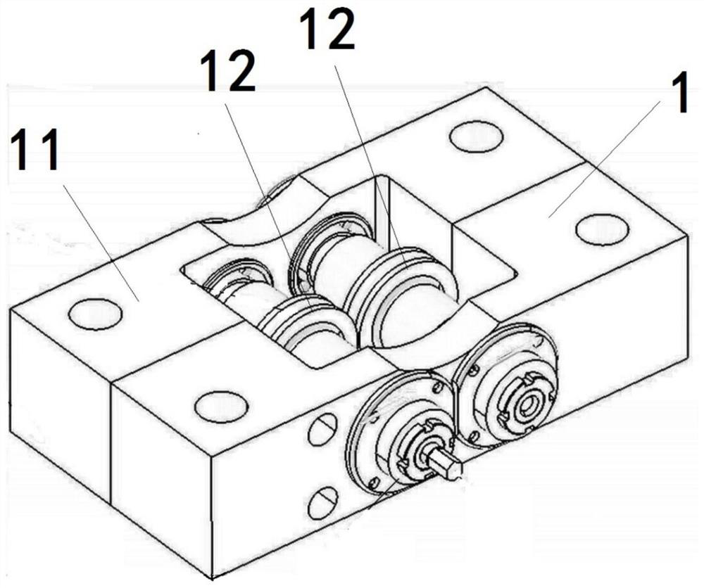
[0080] Such as Figure 1 to Figure 11 As shown, the rolling friction measurement system of t...

specific Embodiment 2

[0097] The difference between it and Embodiment 1 is that in Embodiment 1, threaded holes are provided at both ends of the rigid shaft, and threaded holes are provided beside the mounting holes of the rigid shaft on the upper connectors of the deformation bodies on both sides. After being installed in the mounting hole of the rigid shaft, the two ends of the rigid shaft and the upper connecting blocks of the deformation bodies on both sides are assembled together by bolts to realize the support of the deformation body to the rigid shaft. In this embodiment, the two ends of the rigid shaft are not provided with threaded holes, but are provided with external threads on its peripheral surface, and the rigid shaft installation holes of the upper connecting blocks of the deformation bodies on both sides penetrate the upper connecting block axially, and the rigid shaft Internal thread is provided in the mounting hole. After the two ends of the rigid shaft are screwed into the rigid s...

specific Embodiment 3

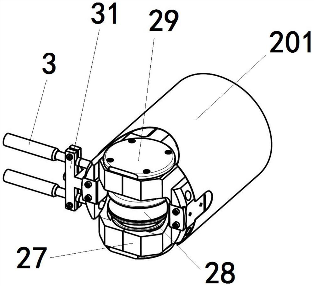
[0099] The main difference between it and Embodiment 1 is that in Embodiment 1, the grating scale base and the loading sleeve are set separately, and are assembled with the loading sleeve through bolts to support and install the grating scale on the outer peripheral surface of the loading sleeve. In this embodiment, the grating scale base is canceled, and the bottom of the outer peripheral surface of the loading sleeve is provided with a protruding block-shaped structure. The protruding block-shaped structure is provided with a round hole for inserting the grating scale base, and then the grating scale is supported and installed on the The outer peripheral surface of the loading sleeve makes the grating scale and the outer peripheral sleeve obtain a higher synchronization rate.


PUM


Abstract

The invention relates to a bearing rolling body rolling friction force measuring system and a loading device thereof, and the system comprises: a test bench, wherein the loading device is supported and matched above the test bench, a loading support is correspondingly provided with a loading sleeve, and the loading support is in transmission connection with a loading driving mechanism; a loading sleeve, wherein a wheel seat and a loading wheel are arranged in the loading sleeve; a wheel seat, wherein a loading wheel is rotationally assembled on the wheel seat; a loading wheel which axially extends in the front-back direction and is used for being in direct contact with the bearing rolling body and loading the bearing rolling body in the radial direction of the bearing rolling body; and deformable bodies on the two sides which are arranged in bilateral symmetry about the central axis of the loading wheel, the upper ends of the deformable bodies can swing left and right relative to the lower ends of the deformable bodies, the upper ends of the deformable bodies are fixedly connected with the wheel seat, and the lower ends of the deformable bodies are fixedly connected with the loading sleeve. According to the system for measuring the rolling friction force of the bearing rolling body, the bearing rolling body is separated from the rolling bearing, so that the interference of other factors in the bearing during the measurement of the rolling friction force of the bearing rolling body is eliminated.

Description

technical field [0001] The invention relates to a rolling friction measurement system of a bearing rolling body and a loading device thereof. Background technique [0002] Rolling bearings are very common parts in machines, which rely on the rolling contact between the main parts to support the rotating parts. Most of the rolling bearings in the prior art have been standardized, mainly including an inner ring, an outer ring, rolling elements and a cage, and the rolling elements correspond to the inner ring and the outer ring to form a friction pair in the rolling bearing. When the rolling element is working, it will slide and roll relative to the inner ring and the outer ring at the same time. The magnitude and direction of the friction force on the rolling element are complex and changeable. In order to ensure the service life and reliability of the rolling element and rolling bearing, it is necessary to Test and evaluate various friction and wear properties of rolling ele...

Claims


Application Information

Patent Timeline
Patent Type & Authority Applications(China)
IPC IPC(8): G01M13/04G01N19/02
CPCG01M13/04G01N19/02Y02E10/72
Inventor 路菲逄显娟刘方涛杨勇贺甜甜刘建张永振
Owner HENAN UNIV OF SCI & TECH
Why Eureka
Try Eureka