Wing based on variable-camber flexible trailing edge and gust response retarding method thereof

A wing and trailing edge technology, applied in the field of wing gust response mitigation based on variable camber flexible trailing edge, can solve the problem of not fully considering the large deformation nonlinearity of the continuous variable camber trailing edge, the lack of flexible trailing edge structural engineering application examples, Issues such as calculation cycle and difficulty enhancement, to achieve the effect of reducing calculation cost and cycle, improving flight performance, and increasing structural flexibility

Active Publication Date: 2021-07-23
BEIHANG UNIV
View PDF4 Cites 5 Cited by
  • Summary
  • Abstract
  • Description
  • Claims
  • Application Information

AI Technical Summary

Problems solved by technology

[0004] At this stage, the main problem of the existing methods of wing gust mitigation based on the variable camber flexible trailing edge is that there is a lack of engineering application examples of flexible trailing edge structures for gust mitigation; at the same time, the aerodynamic modeling of the trailing edge mainly uses engineering approximation methods, and there is no Fully consider the nonlinear characteristics of the large deformation of the trailing edge with continuously variable camber, and the use of high-precision CFD calculations will greatly increase the calculation cycle and difficulty; in addition, there is a lack of mature and effective gust mitigation control using the trailing edge of the continuously variable camber wing. Control plan

Method used


Image

  • Wing based on variable-camber flexible trailing edge and gust response retarding method thereof
  • Wing based on variable-camber flexible trailing edge and gust response retarding method thereof
  • Wing based on variable-camber flexible trailing edge and gust response retarding method thereof

Examples


Embodiment Construction

[0031] The present invention will be described in further detail below in conjunction with the accompanying drawings.

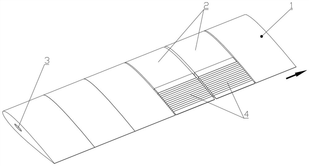
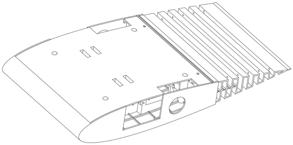
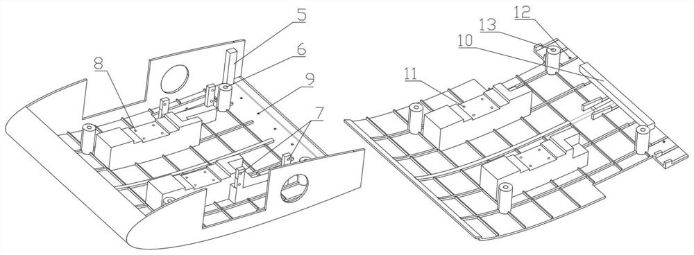
[0032] The invention discloses a wing gust response mitigation method based on the variable camber flexible trailing edge, and designs a variable camber trailing edge structure based on a corrugated plate form for a three-dimensional wing; it adopts a combination of CFD calculation and aerodynamic reduction order identification method The generalized unsteady aerodynamic model of the wing is established by the traditional panel method, which is coupled with the structural dynamics model of the wing to obtain the gust response model of the wing, and an active control scheme for gust mitigation is given for the wing.

[0033] According to an embodiment of the present invention, the method for mitigating the gust response of the wing based on the variable camber flexible trailing edge includes:

[0034] Step 1. For the three-dimensional wing, design a variable c...


PUM


Abstract

The invention discloses a gust response retarding method of a wing based on a variable-camber flexible trailing edge, and relates to the field of gust mitigation control of flexible aircrafts. The method comprises the steps of firstly, designing a flexible trailing edge structure based on a corrugated plate form for a certain type of wing; then, establishing a wing finite element model to obtain corresponding modal information; thirdly, identifying training data obtained through CFD by an observer method, and creating a wing trailing edge deflection generalized unsteady aerodynamic force reduced-order model; utilizing a surface element method to calculate modal and gust aerodynamic force; establishing a wing open-loop gust response model by the aerodynamic model and the modal information; and finally, adopting a flexible trailing edge as a control surface, taking the wingtip acceleration as a feedback input signal, calculating and designing a closed-loop control law by a GPC method, and adding a closed loop based on open-loop response to obtain an overall wing gust response closed-loop active control system. The variable-camber flexible trailing edge is adopted to slow down the gust response of the wing, the gust response can be effectively slowed down, and compared with a conventional wing, the variable-camber flexible trailing edge wing has greater advantages in the aspects of aerodynamic characteristics and structural quality.

Description

technical field [0001] The invention relates to the fields of flexible aircraft design and gust mitigation, in particular to a method for mitigating wing gust response based on variable camber flexible trailing edges. Background technique [0002] With the continuous advancement of active control technology in the field of aviation technology, people have gradually realized that the flexibility of the structure can play a greater potential with the support of active control technology, resulting in the concept of adaptive wings. Fixed wing, which can automatically change the shape of the wing with the change of flight conditions such as Mach number, angle of attack, atmospheric disturbance and maneuvering flight, thereby changing the flow of the wing surface and reducing separation, so that it can be used in every flight state Both can obtain the maximum lift-to-drag ratio and lift coefficient. Due to the important contribution of camber to lift, among many variant forms, v...

Claims


Application Information

Patent Timeline
Patent Type & Authority Applications(China)
IPC IPC(8): G06F30/15G06F30/23G06F30/28B64C3/36B64C3/28B64C5/10G06F113/08G06F113/10G06F119/14
CPCG06F30/15G06F30/23G06F30/28B64C3/36B64C3/28B64C5/10G06F2113/08G06F2113/10G06F2119/14Y02T90/00
Inventor 戴玉婷尉濡恺杨超
Owner BEIHANG UNIV
Why Eureka
Try Eureka