High-gain antenna with microstrip patch antenna loaded with periodic structure

A technology of microstrip patch antenna and periodic structure, which is applied in the direction of resonant antenna, radiating element structure, basically flat resonant element, etc., can solve the problems of complex feeding network, expensive, large volume, etc., and achieve high gain Features, simple structure, high gain effect

Active Publication Date: 2021-07-23
SUN YAT SEN UNIV
View PDF1 Cites 0 Cited by
  • Summary
  • Abstract
  • Description
  • Claims
  • Application Information

AI Technical Summary

Problems solved by technology

At present, the types of high-gain antennas include parabolic reflector antennas, planar array antennas, and horn antennas. Traditional parabolic reflector antennas and horn antennas have simple feed sources, but they are large in size and expensive; and parallel array antennas have high gain. , easy to integrate, but its feed network is complicated and the cost is high

Method used


Image

  • High-gain antenna with microstrip patch antenna loaded with periodic structure
  • High-gain antenna with microstrip patch antenna loaded with periodic structure
  • High-gain antenna with microstrip patch antenna loaded with periodic structure

Examples


Embodiment Construction

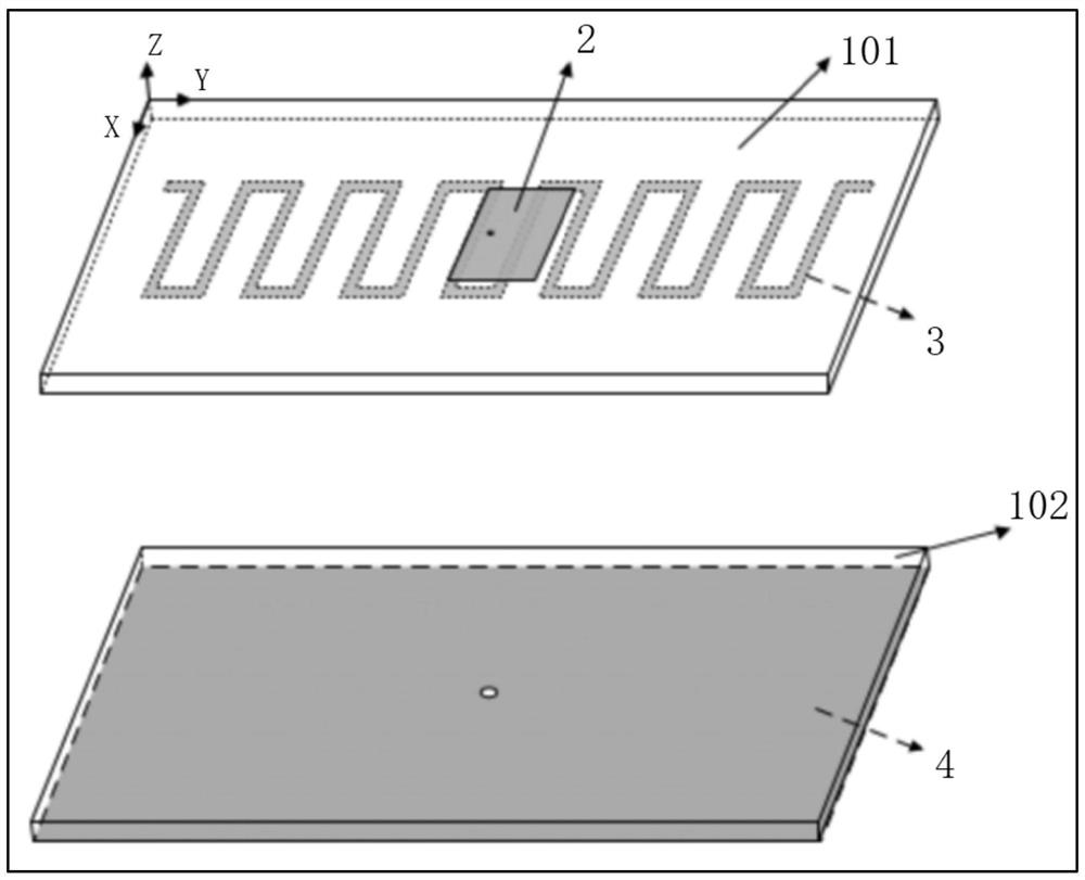
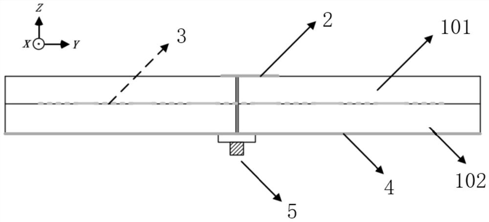
[0024] In this example, refer to figure 1 The microstrip patch antenna is loaded with a periodic structure high-gain antenna, including a dielectric plate, a metal radiator, a metal floor, and a periodic leaky wave structure. Among them, the dielectric board is a double-layer structure, the first dielectric layer and the second dielectric layer of the dielectric board, the lower surface of the first dielectric layer is relatively attached to the upper surface of the second dielectric layer, and the periodic leaky wave structure is embedded in the first dielectric layer Between the layer and the second dielectric layer, the upper surface of the first dielectric layer forms the upper surface of the dielectric plate, and the lower surface of the second dielectric layer forms the lower surface of the dielectric plate. A metal radiator is fabricated on the upper surface of the dielectric board by a microstrip process, and a metal floor is fabricated on the lower surface of the diel...


PUM


Abstract

The invention discloses a high-gain antenna with a microstrip patch antenna loaded with periodic structure, which comprises a dielectric plate, a metal radiator, a metal floor and a periodic leaky wave structure, wherein the structural parameters of the periodic leaky wave structure are set as determined values in an adjustable or solidified manner; and at least one frequency point generated by the periodic leaky wave structure is enabled to be the same as a resonance point of the antenna. The periodic leaky wave structure is embedded in the dielectric plate of the microstrip patch antenna, and the effective dielectric constant of the dielectric plate is changed, so that the electric field distribution of the metal radiator is changed, a relatively high gain can be achieved, and the antenna can obtain a high gain characteristic by adjusting the periodic leaky wave structure. In addition, the high-gain antenna with the microstrip patch antenna loaded with the periodic structure is of a planar structure, the structure is simple, and batch processing and production are facilitated. The high-gain antenna is applied to the technical field of wireless communication.

Description

technical field [0001] The invention relates to the technical field of wireless communication, in particular to a microstrip patch antenna loaded with a periodic structure high-gain antenna. Background technique [0002] With the development of modern mobile communication technology, the continuous improvement of the frequency band used by electromagnetic waves, and the continuous increase of communication distance, the research of high-gain antennas is becoming more and more important, so it has gradually become one of the research hotspots in the field of antennas. At present, the types of high-gain antennas include parabolic reflector antennas, planar array antennas, and horn antennas. Traditional parabolic reflector antennas and horn antennas have simple feed sources, but they are large in size and expensive; and parallel array antennas have high gain. , The advantages of easy integration, but its feed network is complex and the cost is high. Contents of the invention ...

Claims


Application Information

Patent Timeline
Patent Type & Authority Applications(China)
IPC IPC(8): H01Q1/38H01Q9/04
CPCH01Q1/38H01Q9/0407
Inventor 陈晓宁李元新龙云亮
Owner SUN YAT SEN UNIV
Why Eureka
Try Eureka