Ultrasonic contrast imaging method and device and storage medium

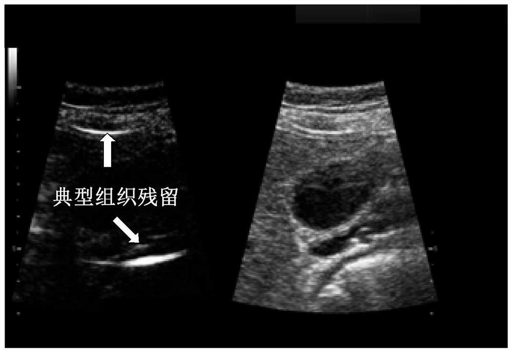
An imaging method and contrast-enhanced ultrasound technology, applied in ultrasound/sonic/infrasound image/data processing, ultrasonic/sonic/infrasonic diagnosis, ultrasonic/sonic/infrasonic Permian technology, etc. It is difficult to improve, and problems occur in blood vessel walls, organ capsules and bones, so as to suppress the residual part of the tissue without affecting the strength of the contrast agent

Active Publication Date: 2021-07-23
SHENZHEN MINDRAY BIO MEDICAL ELECTRONICS CO LTD
View PDF8 Cites 0 Cited by
  • Summary
  • Abstract
  • Description
  • Claims
  • Application Information

AI Technical Summary

Problems solved by technology

[0003] In addition, there are three factors that can lead to residual tissue
One is that the tissue itself also produces nonlinear components, which are detected together with the nonlinear echo of the contrast agent; the other is that due to signal saturation, the linear components of the tissue cannot be canceled after the amplitude of each pulse is modulated in nonlinear imaging methods , often appear on strong reflective surfaces such as blood vessel walls, organ capsules, and bones; third, movement during the scanning process (probe displacement, patient breathing, etc.) will lead to the loss of correlation of each pulse echo in nonlinear imaging methods, Then the condition of tissue signal cancellation is not satisfied
[0004] Tissue residues will interfere with the user's observation of contrast agent signals, thereby affecting the accuracy of diagnostic results
In this regard, the existing solutions start with the front-end hardware on the one hand, and study how to further improve the symmetry of the transmitted waveform, but the improvement is extremely difficult; on the other hand, new imaging methods (subharmonics, etc.) or signal processing methods (filtering etc.) to suppress tissue residues as much as possible, but in addition to the nonlinear components produced by the tissue itself, tissue residues caused by other reasons and contrast agent signals cannot be distinguished in the frequency domain, and the suppression ability is limited

Method used


Image

  • Ultrasonic contrast imaging method and device and storage medium
  • Ultrasonic contrast imaging method and device and storage medium
  • Ultrasonic contrast imaging method and device and storage medium

Examples


Embodiment Construction

[0032] In order to make the objects, technical solutions, and advantages of the present application more apparent, exemplary embodiments according to the present application will be described in detail below with reference to the accompanying drawings. Apparently, the described embodiments are only some of the embodiments of the present application, rather than all the embodiments of the present application. It should be understood that the present application is not limited by the exemplary embodiments described here. Based on the embodiments of the present application described in the present application, all other embodiments obtained by those skilled in the art without creative efforts shall fall within the protection scope of the present application.

[0033] In the following description, numerous specific details are given in order to provide a more thorough understanding of the present application. It will be apparent, however, to one skilled in the art that the present...


PUM


Abstract

An ultrasound contrast imaging method and device, and a storage medium. The method comprises: acquiring at least two frames of contrast data (S310); calculating an information difference between two adjacent frames of contrast data, and calculating a relationship between the information difference and one frame of contrast data in the two adjacent frames of contrast data (S320); and classifying the one frame of contrast data based on the relationship, and performing suppression processing on at least partial data of the one frame of contrast data based on the classification result (S330). According to the method, the difference between the tissue residue and the contrast agent signal is mined from the angle of time domain difference (inter-frame difference), and the tissue residue part and the contrast agent signal part in the contrast data can be effectively distinguished, so that the tissue residue part can be effectively inhibited, and the intensity of the contrast agent is not influenced as far as possible.

Description

technical field [0001] The present application relates to the technical field of contrast-enhanced ultrasound imaging, and more specifically relates to a method, device and storage medium for contrast-enhanced ultrasound imaging. Background technique [0002] Under ideal conditions, only background noise exists in CEUS images without contrast agent injection. However, in actual situations, it is inevitable to introduce tissue components while extracting contrast agent signals, which is mainly caused by the asymmetry of the system’s transmitting circuit. Taking the positive and negative harmonic method as an example, in theory, two waveforms with the same amplitude and frequency and opposite phase can be completely canceled after being superimposed. However, the positive and negative pulses output by the actual transmitting circuit are not strictly symmetrical, and residual The signal, reflected in the contrast image, is the tissue residue. [0003] In addition, there are t...

Claims


Application Information

Patent Timeline
Patent Type & Authority Applications(China)
IPC IPC(8): A61B8/08
CPCA61B8/481A61B8/5207A61B8/5269
Inventor 章希睿桑茂栋朱磊何绪金
Owner SHENZHEN MINDRAY BIO MEDICAL ELECTRONICS CO LTD
Why Eureka
Try Eureka