Numerical control cutting method for preventing inner hole notch of thick plate part

A cutting method and inner hole technology, used in welding equipment, gas flame welding equipment, metal processing equipment, etc., can solve the problems of unsatisfactory cutting quality improvement effect, consumption of manpower and material resources, cutting notch damage to parts, etc., to reduce artificial The effect of modifying workload, reducing manpower and material resources, and improving cutting quality and efficiency

Pending Publication Date: 2021-07-27
中国船舶集团渤海造船有限公司
View PDF7 Cites 2 Cited by
  • Summary
  • Abstract
  • Description
  • Claims
  • Application Information

AI Technical Summary

Problems solved by technology

[0003] When flame CNC cutting the inner hole of large and thick plate parts, due to the unstable state of cutting voltage, current, cutting gas pressure, nozzle and other factors, arc craters will appear at the introduction position of inner hole cutting, that is, at the arc extinguishing point of inner hole cutting Cutting gaps hurt parts, leading to quality problems of cutting defects in parts. The thicker the plate, the higher the probability of defects.
After the defect occurs, it is necessary to manually repair the cutting gap and then manually polish and smooth it, which consumes a lot of manpower and material resources
For this reason, people have taken measures such as arc-shaped leads tangent to the inner hole, setting back secant lines, etc., but the effect of improving the cutting quality is not ideal, and the cutting gap still occurs. The root cause is that the cutting introduction position of the inner hole and the The arc extinguishing point of hole cutting is at the same position, and the cutting seam has a width. When the torch runs to the arc extinguishing point, it is equivalent to cutting twice at the same position, and a cutting gap will be generated at the arc extinguishing point.

Method used


Image

  • Numerical control cutting method for preventing inner hole notch of thick plate part
  • Numerical control cutting method for preventing inner hole notch of thick plate part

Examples


Embodiment

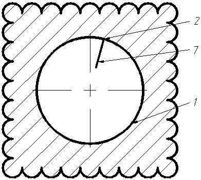
[0023] As shown in the figure, taking a part with a thickness of 55mm and an inner hole diameter of 100mm as an example, the cutting steps and process are specifically explained for the modification of the inner hole contour and the setting of cutting parameters.

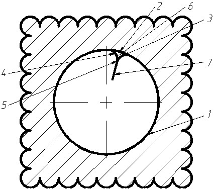
[0024] (1) First, modify the parts library file, identify a part in the parts library whose thickness is 55 mm and the diameter of the inner hole is 100 mm, modify the identified part inner hole geometry in AutoCAD software, and decompose the part geometry into straight line segments and Arc line: select the midpoint 2 of the inner hole contour line 1 of the part, and make a right inscribed arc line 3 with a radius of 10 mm on the inner side of the part inner hole and the left and right sides of the midpoint respectively. The intersection of the side inscribed arc line 4, the right inscribed arc line 3 and the left inscribed arc line 4 is the arc extinguishing point 5 during CNC flame cutting, and the distance betwee...


PUM

PropertyMeasurementUnit
thicknessaaaaaaaaaa
lengthaaaaaaaaaa
thicknessaaaaaaaaaa

Abstract

The invention provides a numerical control cutting method for preventing an inner hole notch of a thick plate part. Geometric figures of parts are modified in batches by means of programming in AutoCAD software; an arc blowout point, a kerf compensation and a cutting parameter during numerical control flame cutting are set reasonably, such that a crater in an inner hole cutting guidance position of the thick plate part is avoided, and a cutting notch is prevented from being generated at the inner hole cutting arc blowout point to hurt the part, and therefore, the technical problem that the crater occurs on a cut steel plate of a numerical control flame cutter is solved. The geometric figures of parts are modified in batches by means of programming, such that the workload of manual modification is reduced. The arc blowout point, the kerf compensation and the cutting parameter during numerical control flame cutting are set reasonably, such that the crater in an inner hole cutting guidance position of the thick plate part is avoided, and the cutting notch is prevented from being generated at the inner hole cutting arc blowout point to hurt the part, and thus, manpower and material resources consumed to polish and smoothen the edge of the inner hole manually after repair welding of the cutting notch are reduced. The method is suitable for serving as the cutting method for preventing the inner hole notch of the thick plate part.

Description

technical field [0001] The invention relates to the numerical control flame cutting of inner holes of thick plate parts in the field of ships, in particular to a numerical control cutting method for preventing gaps in the inner holes of thick plate parts. Background technique [0002] During the blanking and cutting process of the hull structure, the plates with a thickness below 20mm are generally cut with a CNC plasma cutting machine, and the plates with a thickness of more than 20mm are cut with a CNC flame cutting machine. The setting of the cutting lead is an important process step of flame cutting, which is directly related to the quality of the cutting. The cutting lead is mainly determined by its length and direction, and its length depends on the thickness of the cutting plate. Generally speaking, the thicker the plate, the longer the lead. , without affecting cutting and perforation, in order to improve material utilization, the cutting lead length should be reduce...

Claims


Application Information

Patent Timeline
Patent Type & Authority Applications(China)
IPC IPC(8): B23K7/00
CPCB23K7/002
Inventor 李海波刘民董元涛刘希权赖新阁
Owner 中国船舶集团渤海造船有限公司
Why Eureka
Try Eureka