
Forming equipment with positioning structure for computer graphics card backboard machining

A graphics card backplane and positioning structure technology, applied in metal processing equipment, welding equipment, manufacturing tools, etc., can solve the problems of inconvenient clamping and fixing of the computer graphics card backplane, inconvenient flexible adjustment of welding forming mechanism, and inability to realize double-sided processing, etc.

Inactive Publication Date: 2021-07-27
长沙市熊亮机电设备有限公司
View PDF0 Cites 6 Cited by
  • Summary
  • Abstract
  • Description
  • Claims
  • Application Information

AI Technical Summary

Problems solved by technology

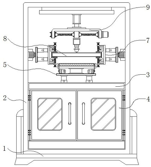
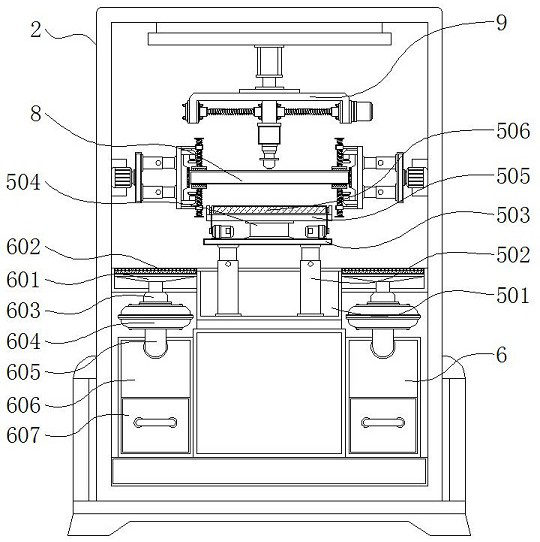
[0004] The purpose of the present invention is to provide a molding device with a positioning structure for processing the backboard of a computer graphics card, so as to solve the problem that the existing molding equipment for processing the backboard of a computer graphics card proposed in the background technology is not convenient for comparing the backboard of a computer graphics card. High-precision clamping and fixing, and does not have the function of turning over processing, cannot realize double-sided processing, and is not convenient for flexible adjustment of processing mechanisms such as welding and forming mechanisms

Method used


Image

  • Forming equipment with positioning structure for computer graphics card backboard machining
  • Forming equipment with positioning structure for computer graphics card backboard machining
  • Forming equipment with positioning structure for computer graphics card backboard machining

Examples


Embodiment Construction

[0026] The technical solutions in the embodiments of the present invention will be clearly and completely described below in conjunction with the accompanying drawings in the embodiments of the present invention. Obviously, the described embodiments are only some of the embodiments of the present invention, not all of them. Based on The embodiments of the present invention and all other embodiments obtained by persons of ordinary skill in the art without making creative efforts belong to the protection scope of the present invention.

[0027] In the description of the present invention, unless otherwise stated, the meaning of "plurality" is two or more; the terms "upper", "lower", "left", "right", "inner", "outer" , "front end", "rear end", "head", "tail", etc. indicate the orientation or positional relationship based on the orientation or positional relationship shown in the drawings, and are only for the convenience of describing the present invention and simplifying the desc...


PUM


Abstract

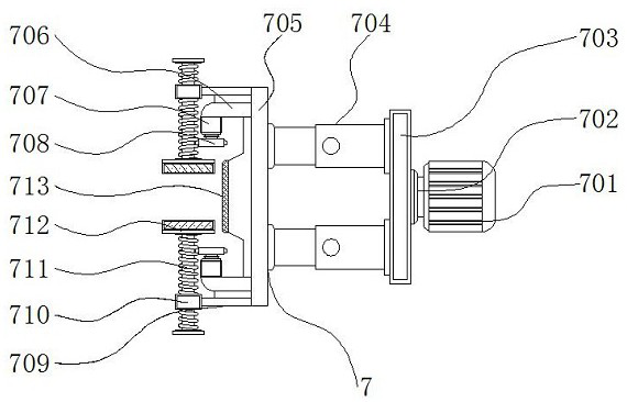
The invention discloses forming equipment with a positioning structure for computer graphics card backboard machining, and relates to the technical field of computer graphics card backboard machining. The forming equipment comprises an equipment outer frame, a positioning clamping mechanism and a welding forming mechanism, a base is arranged under the equipment outer frame, and a workbench is fixed in the middle of the interior of the equipment outer frame; and an opening and closing door is mounted on the outer side of the lower portion of the equipment outer frame and connected with the equipment outer frame through hinges, and a feeding mechanism is arranged on the upper portion of the middle of the workbench and comprises a mounting frame, hydraulic push rods, a supporting plate, a bearing column, a bearing plate and a conveying belt. The forming equipment has the beneficial effects that the positioning clamping mechanism of the forming equipment is provided with gears and threaded rods, the gears are conveniently driven to rotate through a micro motor, the gears and the threaded rods are of an engaged structure so that the rotating gears can drive the threaded rods to move up and down, the positions of positioning plates at one ends of the threaded rods can be conveniently adjusted, and attaching gaps of the positioning plates is reduced.

Description

technical field [0001] The invention relates to the technical field of computer graphics card backplane processing, in particular to a forming device with a positioning structure for processing a computer graphics card backplane. Background technique [0002] The graphics card is used to process the display screen. The graphics card is an important part of the computer host. The purpose of the graphics card is to convert and drive the display information required by the computer system, and to provide line scan signals to the monitor to control the correct display of the monitor. It is an important component to connect the monitor and the motherboard of the personal computer. The actual purpose of the graphics card backplane is to strengthen the graphics card to prevent the graphics card PCB from being deformed. The second is to be more beautiful. In the process of processing the computer graphics card backplane, molding equipment is used. [0003] The existing molding equip...

Claims


Application Information

Patent Timeline
Patent Type & Authority Applications(China)
IPC IPC(8): B23K37/02B23K37/04B23K37/00B08B5/04B08B15/04
CPCB08B5/04B08B15/04B23K37/00B23K37/0247B23K37/0443
Inventor 卢本雄莫超微莫梓旋
Owner 长沙市熊亮机电设备有限公司
Learn More