Rapid drying assembly line for printed articles

A rapid drying and assembly line technology, applied in the direction of printing, printing machines, general parts of printing machinery, etc., can solve the problems of unable to adapt to plate-shaped paper boards, low conveyor belt spacing, etc., to achieve active gas flow, good diffusion of hot air , Enhance the effect of drying efficiency

Pending Publication Date: 2021-07-27
林晗辉
View PDF8 Cites 1 Cited by
  • Summary
  • Abstract
  • Description
  • Claims
  • Application Information

AI Technical Summary

Problems solved by technology

[0004] Place the printed materials to be dried on the conveyor belt in the drying equipment, and by controlling the speed, the items enter the drying box at intervals, because the drying box runs through the conveyor belt in order not to disperse the internal heat. The front and re

Method used


Image

  • Rapid drying assembly line for printed articles
  • Rapid drying assembly line for printed articles
  • Rapid drying assembly line for printed articles

Examples


Embodiment 1

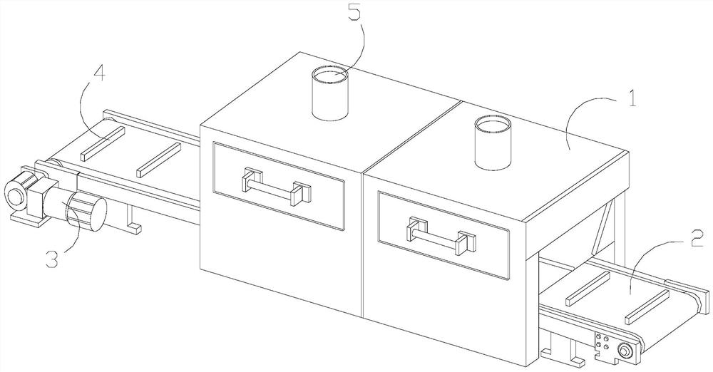
[0031] as attached figure 1 to attach Figure 7 Shown:

[0032] The present invention provides a quick drying assembly line for printed articles. Its structure is provided with a drying box 1, a conveyor belt 2, a total power 3, a positioning rod 4, and an exhaust port 5. The conveyor belt 2 runs through the inside of the drying box 1. The total power 3 is installed at one side of the conveyor belt 2, the positioning rod 4 and the conveyor belt 2 are integrated, and the exhaust port 5 and the drying box 1 are integrated and connected.

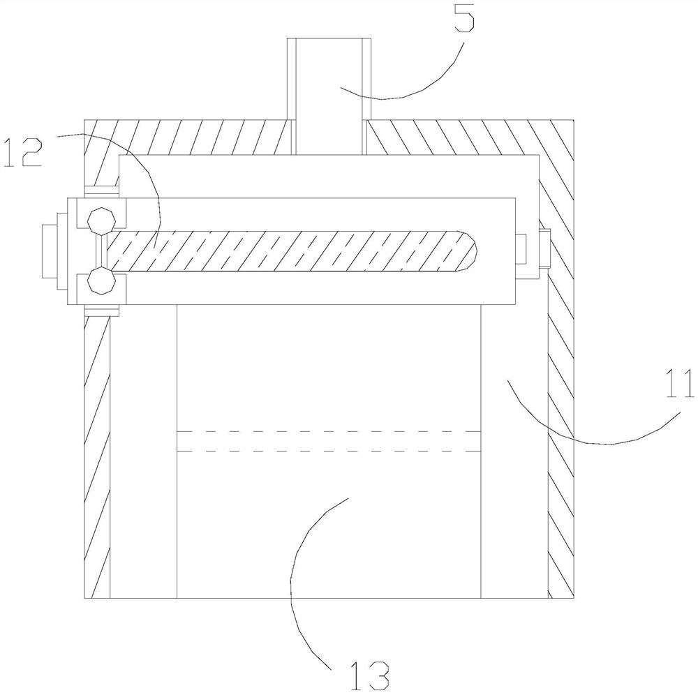
[0033] The drying box 1 is provided with a box frame 11, a heat-producing plate 12, and a passage port 13. The box frame 11 and the drying box 1 are an integrated structure, and the heat-producing plate 12 is embedded in a part of the box frame 11. In the upper position, the passage port 13 is located below the heat generating plate 12 .

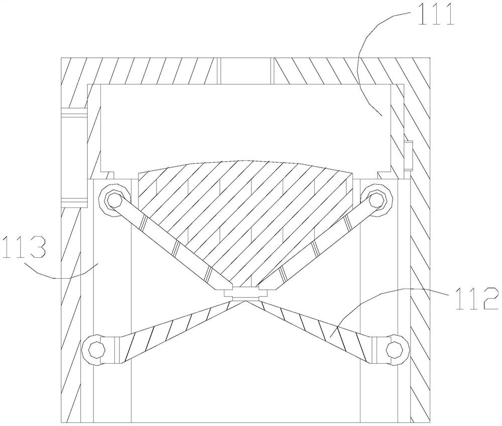
[0034] Wherein, the box frame 11 is provided with a plate top 111, a movable frame 112, and a side cavi...

Embodiment 2

[0041] as attached Figure 8 to attach Figure 9 Shown:

[0042] Wherein, the abutting plate a1 is provided with a solid plate a11, a motion-assisting ball a12, and a hinge pulley a13, the hinge pulley a13 is movably connected to the lower end of the solid plate a11, and the motion-assisting ball a12 is movably installed on the front end surface of the solid plate a11 Above, there are two assisting balls a12, and they are of spherical structure. Under the action of contact with foreign objects, the assisting balls a12 can be displaced and rotated to a certain extent, so as to generate driving force.

[0043] Wherein, the assisting ball a12 is provided with a swivel e1 and a collision spring e2, the front end of the collision spring e2 is connected with the outer side of the swivel e1 in a gap fit and is movably matched, the swivel e1 is a ring structure, and the collision spring e2 is arc-shaped, has elastic force, and can be deformed in the arc direction, and the collision ...


PUM


Abstract

The invention discloses a rapid drying assembly line for printed articles. The rapid drying assembly line is structurally provided with a drying box, a conveying belt, a total power, a positioning rod and an exhaust port; the conveying belt penetrates through the interior of the drying box; and the total power is installed at the position of one side end of the conveying belt. When a plate-shaped printed matter passes through a passing opening, the side end of an abutting plate is collided and pressed in advance; the abutting plate swings and folds at an angle while displacing, the flexible dragging force of a pulling block assists a telescopic frame to stretch out and draw back and fold upwards, the fold shrinkage and folding property of a folded plate facilitates the change of the included angle between the abutting plate and the telescopic frame, a bag block generates a lifting force on a ball block, and the flexible property of a flexible block facilitates the expansion and shrinkage deformation of a condensation block; an arc frame is better extruded to deform and change internal air pressure under elastic dragging of a soft rubber bottom, so that airflow in a variable cavity is extruded to the outer side of a cushion block and acts on the inside of a plate top to better diffuse hot air and activate gas flowability; and the heavy pressure property of a gravity center ball facilitates resetting of a deformation top, so that the abutting plate can conveniently and timely minimize an opening, and the drying efficiency is improved.

Description

technical field [0001] The invention belongs to the field of drying assembly line, and more specifically, relates to a fast drying assembly line for printed articles. Background technique [0002] Printing is the copying and reprinting of graphic information on paper materials. It is the key technology of printing and manufacturing. The drying of printed items is an important link in the printing production process. Use quick-drying equipment to print paper with ink copy information Quality materials are dried in time. [0003] Based on the inventor's discovery above, the existing fast drying assembly line for printed articles has the following deficiencies: [0004] Place the printed materials to be dried on the conveyor belt in the drying equipment, and by controlling the speed, the items enter the drying box at intervals, because the drying box runs through the conveyor belt in order not to disperse the internal heat. The front and rear ports are set at a relatively low...

Claims


Application Information

Patent Timeline
IPC IPC(8): B41F23/04
CPCB41F23/0443B41F23/0466
Inventor 林晗辉
Owner 林晗辉
Why Eureka
Try Eureka