Rotating target binding method capable of removing oxides, computer readable storage medium and binding device

A technology of rotating target and oxide, which is applied in metal material coating process, ion implantation plating, coating, etc., can solve the problem of low bonding rate between indium and target material/back tube, and achieve the goal of improving the bonding rate Effect

Pending Publication Date: 2021-07-27
广州市尤特新材料有限公司
View PDF0 Cites 0 Cited by
  • Summary
  • Abstract
  • Description
  • Claims
  • Application Information

AI Technical Summary

Problems solved by technology

The method of binding with metal indium needs to be injected while heating the indium and maintaining it above the melting point. Metal indium is easily oxidized in the air, which makes the adhesion rate of indium to the target / back tube low.

Method used


Image

  • Rotating target binding method capable of removing oxides, computer readable storage medium and binding device
  • Rotating target binding method capable of removing oxides, computer readable storage medium and binding device
  • Rotating target binding method capable of removing oxides, computer readable storage medium and binding device

Examples


Embodiment 1

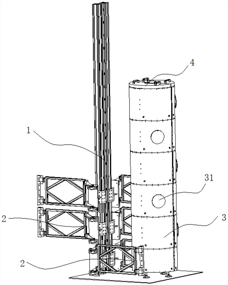
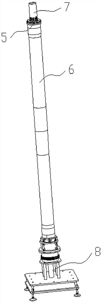
[0026] The binding heating device of the rotating target in this embodiment is as follows: figure 1 with 2 As shown, the rotating target includes a back tube 5 and multiple target tubes 6 , and the binding process is the process of fitting and fixing each segment of the target tube 6 to the outer wall of the back tube 5 in a thermally and electrically conductive manner. In this embodiment, the binding is achieved by pouring indium liquid (binding material) between the back tube 5 and the target tube 6, in which the indium liquid needs to be heated to keep it flowing. The binding heating device used in this embodiment for figure 1 The external heating structure shown in . The external heating structure includes a plurality of ring-shaped heating mantles 3 and heating pipes respectively installed on the inner walls of each heating mantle 3, and multiple heating mantles 3 are coaxially stacked through the bracket 1 and the rotatable clamping part 2, preferably including for Th...

Embodiment 2

[0039] The difference between this embodiment and Embodiment 1 is that another binding device is used, see Figure 4 , the top of the binding device has a large-capacity excess indium solution accommodating cavity 7 . In the binding step, excessive indium liquid is injected so that the washed indium liquid containing oxides floats on the uppermost layer and enters the accommodating chamber 7. After the indium liquid cools down, the indium liquid that falls back to the gap still does not contain The pure indium of the oxide, containing the oxide and / or other impurities floating on the upper layer of the indium liquid remains in the excess indium liquid holding chamber 7 .


PUM

PropertyMeasurementUnit
Thicknessaaaaaaaaaa

Abstract

The invention relates to the technical field of magnetron sputtering target preparation, in particular to a rotating target binding method capable of removing oxides, a target binding device and a computer readable storage medium. According to the rotating target binding method capable of removing the oxides, a hard corrugated sheet extends into a gap between a back tube and the target tubes, the hard corrugated sheet is lifted to scrape the outer surface of the back tube and / or the inner surface of the target tube, indium liquid is injected into the gap upwards from the bottom of the gap between the back tube and the bottommost target tube, and the speed of injecting the indium liquid is controlled, so that the highest point of the indium liquid in the gap is lower than the lowest point of the hard corrugated sheet. According to the rotating target binding method capable of removing the oxides, the indium liquid is injected from bottom to top, the hard corrugated sheet extends into the gap between the back tube and the target tube before the indium liquid is injected, the outer surface of the back tube and the inner surface of the target tube are scraped by utilizing corners of the hard corrugated sheet, and indium oxide layers or other oxides on the back tube and the target tube are removed, so that the laminating rate of indium and the target / back tube is increased.

Description

technical field [0001] The invention relates to the technical field of preparation of magnetron sputtering targets, in particular to a method for binding a rotating target for removing oxides, a computer-readable storage medium, and a binding device for realizing binding by applying the method for removing oxides. Background technique [0002] In recent years, thin film materials prepared by sputtering have been favored by industries such as flat panel displays, electronic controllers, glass coatings, and optical films because of their high density and excellent adhesion. With the rapid development of the above fields, the demand for sputtering targets has increased dramatically. According to the shape of the sputtering surface, targets can generally be divided into planar targets, rotating targets and special-shaped targets. The use of planar target sputtering can reach 30% to 40%, while the utilization rate of rotating target sputtering can reach 80%. The rotating target ...

Claims


Application Information

Patent Timeline
IPC IPC(8): C23C14/35B22D19/04
CPCC23C14/35C23C14/3414B22D19/04
Inventor 雷雨周志宏肖世洪周昭宇汪政军刘芳
Owner 广州市尤特新材料有限公司
Why Eureka
Try Eureka