
Multi-directional connection steel beam-column joint based on dry method connection

A beam-column joint, steel technology, applied in building types, buildings, building components, etc., can solve problems such as affecting the overall mechanical performance of the structure, late start of prefabricated buildings, inconvenient transportation, etc., to reduce construction professionalism and accuracy. performance, ease of transportation and rapid on-site assembly, and the effect of improving economic efficiency

Active Publication Date: 2021-07-27
SOUTHWEST JIAOTONG UNIV
View PDF35 Cites 0 Cited by
  • Summary
  • Abstract
  • Description
  • Claims
  • Application Information

AI Technical Summary

Problems solved by technology

[0004] Due to the late start of my country's prefabricated buildings, basic research is blank in many areas, which cannot provide guidance for engineering practice
Due to the characteristics of assembly, the connection mode and construction characteristics of nodes not only affect the overall mechanical performance of the structure but also affect the production efficiency
At present, my country mainly adopts wet connection, but wet connection affects the construction period and cannot fully utilize the advantages of assembly
Although the dry connection has applications, the structure is complex and difficult to install, and the energy dissipation capacity is seriously insufficient, and the current research mostly adopts the continuous pouring of several-story-high columns, and pre-embeds the connecting components or makes connecting holes in the columns. , as a means of connecting beams to realize the splicing of prefabricated beams
The column length of this dry connection method is relatively large, which is suitable for ordinary areas with convenient transportation, but it has great restrictions for some areas with harsh environments and inconvenient transportation.

Method used


Image

  • Multi-directional connection steel beam-column joint based on dry method connection
  • Multi-directional connection steel beam-column joint based on dry method connection
  • Multi-directional connection steel beam-column joint based on dry method connection

Examples


Embodiment Construction

[0066] In order to make the purpose, technical solutions and advantages of the embodiments of the present invention clearer, the technical solutions in the embodiments of the present invention will be clearly and completely described below in conjunction with the drawings in the embodiments of the present invention. Obviously, the described embodiments It is a part of embodiments of the present invention, but not all embodiments. Based on the embodiments of the present invention, all other embodiments obtained by persons of ordinary skill in the art without making creative efforts belong to the protection scope of the present invention.

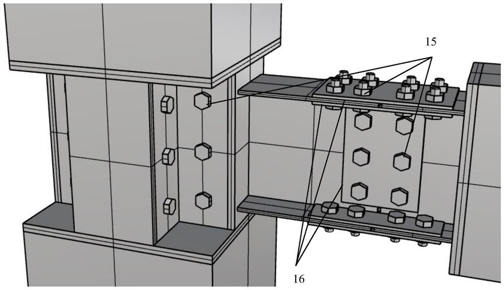
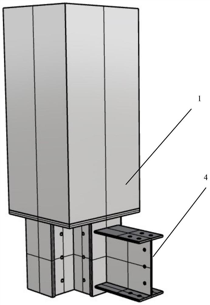
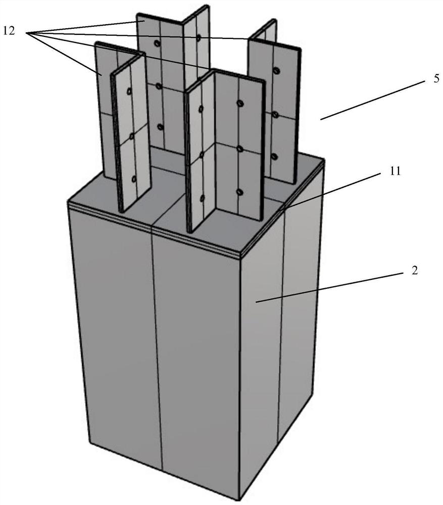
[0067] Such as Figure 1-5 As shown, a multi-directional steel beam-column node based on dry connection in the embodiment of the present application is used to connect with the upper column 1, the lower column 2 and the beam 3, including:

[0068] Upper section steel 4, lower section steel 5 and beam connecting section steel 6;

[0069] The...


PUM


Abstract

The invention provides a multi-direction connection steel beam-column joint based on dry method connection. A beam-column joint core area is replaced with profile steel and serves as a connection joint of the beam-column joint, on-site splicing is carried out through bolts, the height of a prefabricated column can be effectively shortened, transportation and on-site rapid assembly are facilitated, the soft steel of the beam-column joint generates plastic yield hysteresis deformation to dissipate earthquake energy, so that the purposes of energy dissipation and shock absorption are achieved, and a plastic hinge is generated at a specified part to realize controllability and replaceability of the plastic hinge. According to the multi-direction connection steel beam-column joint based on dry method connection, the defect that formwork erecting, concrete cast-in-place and curing still need to be carried out on a construction site in current wet method operation is overcome, the construction efficiency is improved, formwork supports are reduced, and the economic benefits are improved.

Description

technical field [0001] The invention relates to the technical field of building structures, in particular to a multi-directional steel beam-column joint based on dry connection. Background technique [0002] With the continuous advancement of my country's urbanization, the continuous deepening of industrialization, the continuous improvement of people's education level and the continuous aggravation of population aging, my country's demographic dividend is gradually disappearing. The types of construction work with high labor intensity and poor working environment are gradually being abandoned by people. At the same time, traditional construction enterprises are faced with a large amount of labor, large resource consumption, low production efficiency, serious environmental pollution, waste of water resources and other prominent problems that directly restrict the development of the traditional construction industry. In order to solve these problems, the building structure s...

Claims


Application Information

Patent Timeline
Patent Type & Authority Applications(China)
IPC IPC(8): E04H9/02E04B1/98
CPCE04H9/021E04H9/024E04B1/98
Inventor 高文君郑腾虎杨曾徐启阳许浒郭瑞吴昊齐欣赵雷余志祥张豪杰欧盈孙志昂刘肖汇王策李赟
Owner SOUTHWEST JIAOTONG UNIV
Learn More