Gas leakage detection system and method

A gas leak detection and detector technology, which is applied in the detection field, can solve problems such as low detection accuracy and gas leakage, and achieve the effects of enhancing light intensity, reducing detection errors, and preventing gas leakage

Active Publication Date: 2021-07-27
NANJING INST OF TECH
View PDF11 Cites 0 Cited by
  • Summary
  • Abstract
  • Description
  • Claims
  • Application Information

AI Technical Summary

Problems solved by technology

[0004] The purpose of the present invention is to overcome the deficiencies in the prior art, provide a gas leakage detection system and method, and solve the problems in the prior art that the detection accuracy is low and it is not suitable for detecting pipelines without optical fibers

Method used


Image

  • Gas leakage detection system and method
  • Gas leakage detection system and method
  • Gas leakage detection system and method

Examples


Embodiment 1

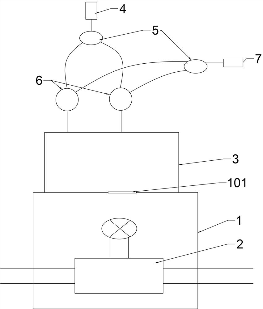
[0032] Such as figure 1 As shown, a gas leak detection system includes a light source 4 capable of emitting light and a detector 8 for detecting light performance. The light source 4 can be a laser, and it only needs to ensure that the light emitted by the light source is stable and not easily affected by other environmental factors. In addition, it also includes a sealed chamber 1, which is sealed outside the place to be measured 2. The upper end surface of the sealed chamber 1 has a small hole, and a deformation device 101 is installed on the hole. The deformation device 101 seals the small hole by bonding, and the sealing method is not limited to bonding, it only needs to ensure that the entire sealing chamber 1 is sealed; the deformation device 101 can use an elastic diaphragm, but it is not limited to this, and can be other materials that are suitable for pressure changes. deformable material, and the sealing chamber 1 is made of rigid material, so as to ensure that the s...

Embodiment 2

[0037] A gas leakage detection system described in Embodiment 1 is used to detect the gas leakage at the place to be tested, and a valve interface of a gas transmission pipeline is selected as the place to be tested. The light intensity value as the prestored light intensity reference value; then collect the light intensity detection value output by the detector 8 at any moment to be measured, compare the collected light intensity detection value with the prestored light intensity reference value, if two If they are not consistent, it indicates that there is an air leak at the test site 2; otherwise, it indicates that there is no air leak at the test site 2.

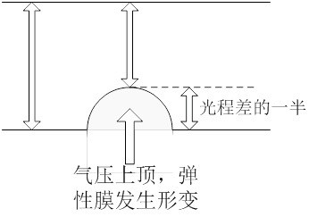
[0038] working principle:

[0039] Such as figure 2 As shown, the deformation device 101 uses an elastic diaphragm; the light source 4 uses a laser; the optical signal splitting element and the optical signal combining element use a coupler; the place to be measured 2 is a gas pipeline valve interface.

[0040]When th...


PUM


Abstract

The invention provides a gas leakage detection system and method. The gas leakage detection system comprises a light source, an optical signal branching element, an optical signal combining element, a sealing cavity and a detector, the sealing cavity is used for sealing a to-be-detected part, a hole is formed in the sealing cavity, and the hole is covered with a deformation device; an optical signal emitted by the light source is divided into two paths through the optical signal branching element, one path is irradiated to the outer wall of the sealing cavity, and the other path is irradiated to the deformation device; the optical signal combining element can enable an optical signal reflected by the outer wall of the sealing cavity and an optical signal reflected by the deformation device to generate double-beam interference; the detector can perform light intensity detection on the light signal after double-beam interference and judges the gas leakage condition according to the light intensity detection result, so the gas leakage condition of the to-be-detected position can be simply, conveniently and visually determined without manual intervention, and sealing treatment can be further performed on the to-be-detected area to prevent gas leakage in the pipeline.

Description

technical field [0001] The invention relates to a gas leakage detection system and method, belonging to the technical field of detection. Background technique [0002] Gas leakage in the pipeline often causes great harm, flammable, explosive or toxic gas, once leakage occurs, it may cause serious consequences such as casualties and environmental pollution. Especially for high-pressure gas pipelines, the consequences of accidents caused are more serious. At present, the hardware detection methods of gas leakage mainly include internal detection method and external detection method, that is, wave detection method based on fluid mechanics, flow balance method, or external inspection method and optical fiber temperature measurement method. These methods not only require a lot of manpower, but also have a lag in detection, making it impossible to detect leakage risks in the first place. [0003] The optical fiber temperature detection method uses the Joule-Thomson effect to det...

Claims


Application Information

Patent Timeline
IPC IPC(8): G01M3/14G01B11/16
CPCG01M3/144G01B11/161
Inventor 魏峘
Owner NANJING INST OF TECH
Why Eureka
Try Eureka