Deflection adjusting device used for wire-drawing die line polishing

A technology of adjusting device and wire drawing die, which is applied to surface polishing machine tools, grinding drive devices, grinding/polishing equipment, etc., can solve the problems of easy wire breakage, unstable work, and large amount of repetitive labor.

Active Publication Date: 2021-07-30
安徽聚芯智造科技股份有限公司
View PDF10 Cites 0 Cited by
  • Summary
  • Abstract
  • Description
  • Claims
  • Application Information

AI Technical Summary

Problems solved by technology

The defect of the above-mentioned existing structure is that the angle deflection between the axis of the drawing die and the axis of the tool wire is currently fixed and adjusted, that is, the drawing die is adjusted to a certain angle and then fixed, and then adjusted each time according to the needs. It is obvious that the adjustment is cumbersome and time-consuming, the amount of repetitive labor is large, and there are unavoidable adjustment errors.
In addition, the above-mentioned fixed-angle adjustment method that needs to be shut down will hinder the continuous and smooth production process, and the original positioning reference may also be shifted due to vibration during work, which makes the traditional line polishing machine have low motion accuracy and processing accuracy. The disadvantage of low processing efficiency is that the work is not stable enough; at the same time, once the fixed angle adjustment is too large, it is easy to break the wire, especially when processing small diameter wire drawing dies, this problem needs to be solved urgently

Method used


Image

  • Deflection adjusting device used for wire-drawing die line polishing
  • Deflection adjusting device used for wire-drawing die line polishing
  • Deflection adjusting device used for wire-drawing die line polishing

Examples


Embodiment Construction

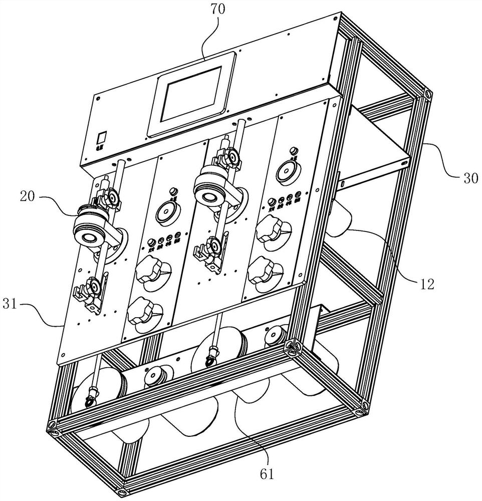
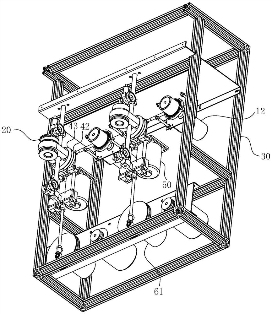
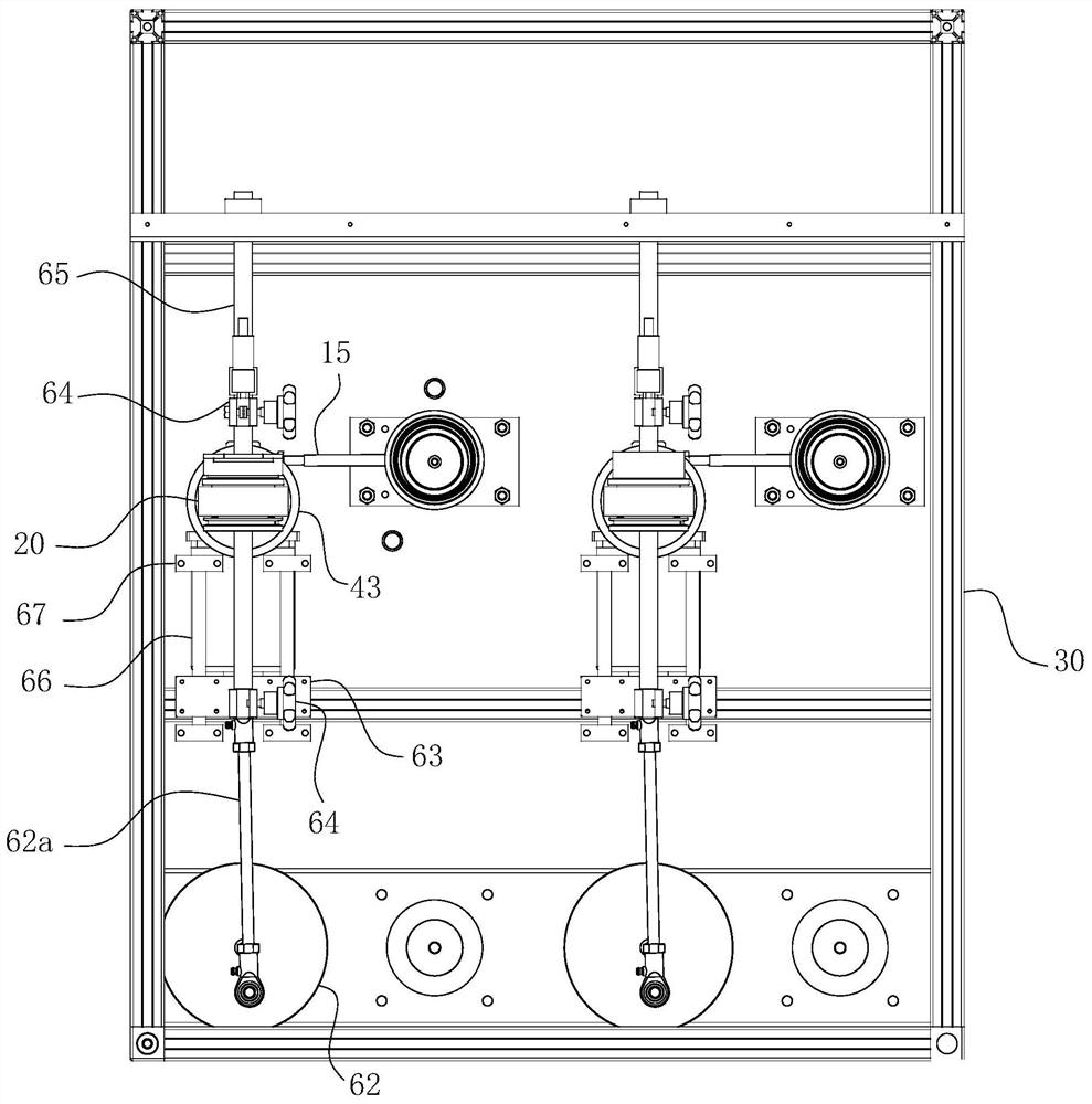
[0049] For ease of understanding, combined here Figure 1-15 , the concrete structure and working mode of the present invention are further described as follows:

[0050] The concrete implementation structure of the present invention refers to Figure 1-15 As shown, it uses the frame 30 as a carrier, and at least a rotary drive module and a yaw adjustment device are arranged on the frame 30 and the panel 31 of the frame 30. The yaw adjustment device is also the present invention, so that when using the rotary Drive the module to rotate the positioning die base 20 to generate a rotary action, so that while the tool wire is used to polish the inner hole of the drawing die a located in the positioning die base 20, the continuous gradual angle adjustment effect of the yaw adjustment device can be used. The purpose of reliable and continuous deflection polishing of the above-mentioned inner hole is achieved. The rotary drive module can be driven by a motor, or a piston cylinder c...


PUM


Abstract

The invention belongs to the technical field of wire-drawing die polishing machining, and particularly relates to a deflection adjusting device used for wire-drawing die line polishing. The deflection adjusting device used for wire-drawing die line polishing comprises a crankshaft, a deflection power source and an eccentric adjusting plate, wherein an eccentric hole is formed in the eccentric adjusting plate in a penetrating mode so that an eccentric section of the crankshaft can be sleeved with the eccentric adjusting plate in a hooped mode, and the eccentric adjusting plate is sleeved with a fixing ring; the outer wall of the fixing ring extends outwards in the radial direction to form a deflection rod, and an extending end of the deflection rod is eccentrically hinged to a rotating shaft; the deflection adjusting device further comprises an outer adjusting sleeve; and a radial adjusting groove is formed in the outer plate face of the eccentric adjusting plate, a guide sliding block is arranged on the inner end face of the outer adjusting sleeve, and the guide sliding block and the radial adjusting groove form a sliding rail guide fit relation. The deflection adjusting device used for wire-drawing die line polishing can match an existing structure of an existing wire-drawing die line polishing machine, and the purpose of wire-drawing die inner hole machining with high efficiency, high quality and convenience is achieved.

Description

technical field [0001] The invention belongs to the technical field of wire drawing die polishing processing, and in particular relates to a deflection adjustment device for wire drawing die line polishing. Background technique [0002] The wire drawing die is a pressure drawing treatment die based on the wire, which can make the wire blank undergo plastic deformation through the die hole under a certain tensile force, so as to achieve the purpose of reducing its cross section and increasing its length; among them, Due to the use of natural diamonds or artificial diamonds as raw materials, diamond drawing dies have strong wear resistance and long service life, and are widely used. The conical compression working area and the cylindrical sizing area of ​​the inner hole of the diamond wire drawing die must have a certain hole shape accuracy and a high degree of smoothness. In order to process the tapered and cylindrical shapes with precise dimensions and high smoothness at th...

Claims


Application Information

Patent Timeline
Patent Type & Authority Applications(China)
IPC IPC(8): B24B19/20B24B29/02B24B41/02B24B41/04B24B41/06B24B47/04B24B47/12B24B47/22
CPCB24B29/02B24B19/20B24B41/02B24B41/04B24B41/06B24B47/04B24B47/12B24B47/22
Inventor 程积龙赵坤荣王松曹磊
Owner 安徽聚芯智造科技股份有限公司
Why Eureka
Try Eureka