
Automatic screwing-on and screwing-off device for sucker rod

A sucker rod and automatic technology, which is applied in the direction of drill pipe, drill pipe, casing, etc., can solve the problems of high-altitude objects falling and hitting, time-consuming installation and disassembly, fatigue-prone operation errors, etc., to achieve convenient operation and speed up the workover process , the effect of reducing the risk of personal injury

Active Publication Date: 2021-08-03
CHINA PETROLEUM & CHEM CORP +2
View PDF9 Cites 1 Cited by
  • Summary
  • Abstract
  • Description
  • Claims
  • Application Information

AI Technical Summary

Problems solved by technology

[0003] In oil production wells produced by machine pumping, the length of sucker rods is mostly 1000m to 2800m. Therefore, the number of sucker rods in a well is large. At present, special manpower tools or hydraulic power tongs are mainly used to lift and lower the sucker rod strings, install and install them. Disassembly is very time-consuming. The operator repeats simple mechanical actions under the heavy-duty lifting equipment for a long time, and is prone to fatigue and operation errors, resulting in personal injury risks such as falling objects from high altitudes, mechanical injuries, etc.

Method used


Image

  • Automatic screwing-on and screwing-off device for sucker rod
  • Automatic screwing-on and screwing-off device for sucker rod
  • Automatic screwing-on and screwing-off device for sucker rod

Examples


Embodiment Construction

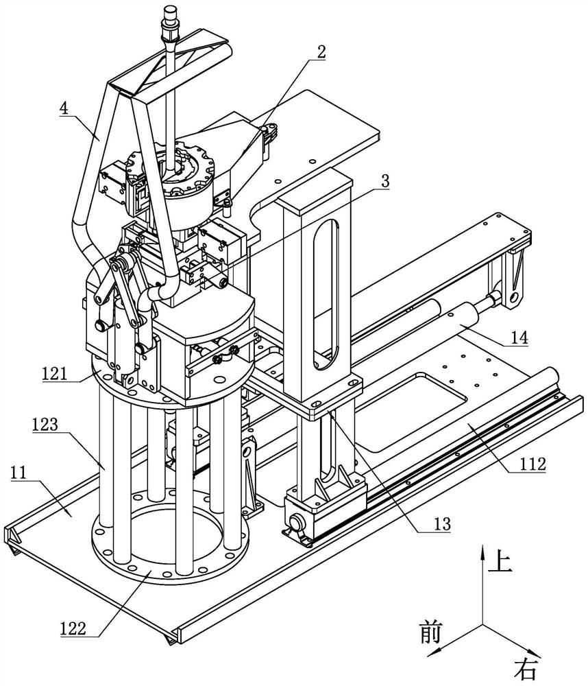
[0050] For the convenience of description, the coordinate system is now defined as figure 1 As shown, the left-right direction is horizontal (row), the front-rear direction is vertical (column), and the up-down direction is vertical.

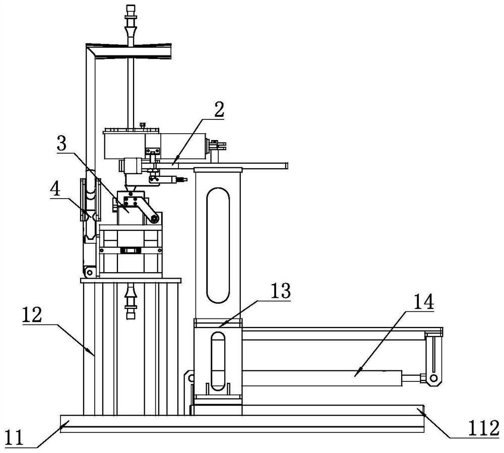
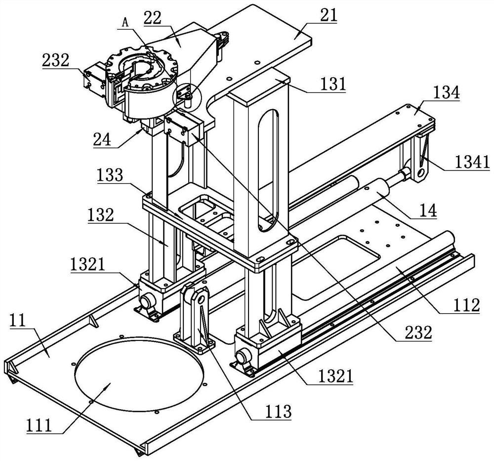
[0051] like figure 1 and figure 2 As shown, a sucker rod automatic make-up and release device includes a main frame body, and the main frame body is provided with an escape hole for accommodating the sucker rod, and the escape hole vertically penetrates the main frame. The main frame body is provided with a slip mechanism 3 above the avoidance hole, and a power tong 2 that can slide back and forth relative to the main frame body is disposed above the slip mechanism 3 . A driving component 14 for driving the power tong 2 to slide back and forth is arranged between the power tong 2 and the main frame body. The fixed side of the driving component 14 is connected with the main frame body, and the driving component The moving side of 14 is conne...


PUM


Abstract

The invention discloses an automatic screwing-on and screwing-off device for a sucker rod, and relates to the technical field of well repairing equipment. The automatic screwing-on and screwing-off device for the sucker rod specifically comprises a bottom plate, wherein a righting mechanism, a slip mechanism and a pair of power tongs are sequentially arranged on the bottom plate from front to back; and the pair of power tongs is located above the slip mechanism. The slip mechanism is fixedly connected with the bottom plate through a supporting frame, the pair of power tongs is connected with the bottom plate in a sliding mode through a sliding frame, and a driving component used for driving the sliding frame to slide is arranged between the sliding frame and the bottom plate. The pair of power tongs comprises a mounting plate, a main tong and an auxiliary tong are arranged on the upper side and the lower side of the mounting plate respectively, and a clamping assembly used for clamping a coupling is arranged between the main tong and the auxiliary tong. The clamping assembly comprises clamping blocks which are symmetrically arranged, and clamping oil cylinders are arranged between the clamping blocks and the mounting plate. According to the automatic screwing-on and screwing-off device for the sucker rod provided by the invention, the mounting and dismounting speed of the sucker rod can be effectively improved, the well repairing process is accelerated, meanwhile, the personal injury risk of well head operators in the oil field well repairing operation is reduced, and the intrinsic safety is realized.

Description

technical field [0001] The invention relates to the technical field of workover equipment, in particular to an auxiliary device used for disassembly and assembly of sucker rods in workover operations. Background technique [0002] Oilfields often use a combination of oil pump and sucker rod string to lift crude oil to the ground, where the sucker rod string is formed by connecting multiple oil rods with a length of about 8m through threaded connection. The process of pulling out the oil rod in the well is to use the workover lifting equipment to lift the sucker rod upwards from the production wellbore, so that the sucker rod connecting coupling is exposed to the workover operation platform, and then the weight of the whole sucker rod string is clamped. For special equipment, the seat position is the square neck of the first sucker rod in the well, and then the sucker rod is removed from the connecting thread with special human tools or hydraulic power tongs, and then continu...

Claims


Application Information

Patent Timeline
Patent Type & Authority Applications(China)
IPC IPC(8): E21B19/16E21B19/10
CPCE21B19/16E21B19/10
Inventor 宋其仓申忠玺陶桂荣何双军王超周水元刘梨
Owner CHINA PETROLEUM & CHEM CORP
Learn More