
CFET structure, preparation method thereof and semiconductor device applying CFET structure

A device and channel structure technology, which is applied in semiconductor devices, semiconductor/solid-state device manufacturing, electric solid-state devices, etc., can solve the problem of difficult to control the balance of NMOS and PMOS, the inability to optimize electron and hole mobility at the same time, and the performance of NMOS devices. To achieve the effect of simultaneously optimizing performance, improving device performance, and optimizing channel crystal orientation

Pending Publication Date: 2021-08-03
INST OF MICROELECTRONICS CHINESE ACAD OF SCI
View PDF0 Cites 0 Cited by
  • Summary
  • Abstract
  • Description
  • Claims
  • Application Information

AI Technical Summary

Problems solved by technology

[0003] In the current CFET structure manufactured by the epitaxial channel method, PMOS is usually placed on the bottom layer, and NMOS is placed on the top layer, so as to facilitate the application of stress on the bottom PMOS device and improve the performance of the PMOS device; The low income of the scheme makes the performance of the top-layer NMOS device very poor, and it is difficult to adjust the balance between NMOS and PMOS; hole mobility

Method used


Image

  • CFET structure, preparation method thereof and semiconductor device applying CFET structure
  • CFET structure, preparation method thereof and semiconductor device applying CFET structure
  • CFET structure, preparation method thereof and semiconductor device applying CFET structure

Examples


Embodiment Construction

[0033] Hereinafter, embodiments of the present invention will be described with reference to the drawings. It should be understood, however, that these descriptions are exemplary only and are not intended to limit the scope of the present invention. Also, in the following description, descriptions of well-known structures and techniques are omitted to avoid unnecessarily obscuring the concept of the present invention.

[0034] Various structural schematic diagrams according to embodiments of the present invention are shown in the drawings. The figures are not drawn to scale, with certain details exaggerated and possibly omitted for clarity of presentation. The shapes of the various regions and layers shown in the figure, as well as their relative sizes and positional relationships are only exemplary, and may deviate due to manufacturing tolerances or technical limitations in practice, and those skilled in the art will Regions / layers with different shapes, sizes, and relative...


PUM


Abstract

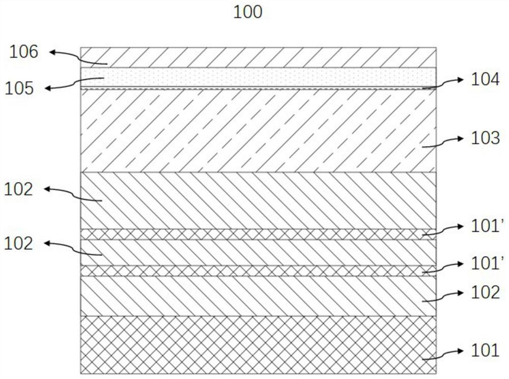
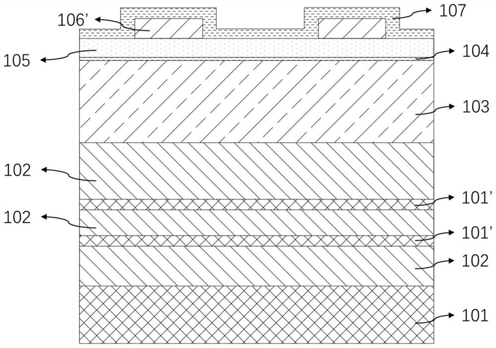
The invention relates to a CFET structure, a preparation method thereof and a semiconductor device applying the CFET structure. Specifically, the method comprises the steps: providing a substrate, forming a basic fin structure on the substrate, and forming a first stack part and a second stack part on a basic fin, wherein the second stack part is vertically stacked on the first stack part, the first stack part is provided with at least one I-type channel structure, the second stack part is provided with at least one II-type channel structure, and the crystal face direction of the I-type channel structure in the first stack part is perpendicular to the crystal face direction of the II-type channel structure in the second stack part; forming a first surrounding gate structure, wherein the first surrounding gate structure is arranged around the I-type channel structure; and forming a second wrap-around gate structure which is disposed around the type II channel structure. Compared with the prior art, the invention has the beneficial technical effects that the vertical integration of the Vertical Nano-sheet and the Horizontal Nano-sheet is realized by utilizing a method of combining side wall masking and selective step-by-step etching, the purpose of simultaneously optimizing the crystal orientations of the NMOS and the PMOS is achieved, and the simultaneous optimization of the performances of the NMOS and the PMOS on a single wafer is realized.

Description

technical field [0001] The invention relates to the technical field of semiconductor integration, in particular to a preparation method of a CFET structure and a semiconductor device. Background technique [0002] In the complementary field-effect transistor (Complementary Field-Effect Transistor, CFET) device structure, nFET and pFET share a gate electrode as a signal input terminal, share a drain electrode as a signal output terminal, and source electrodes are grounded and powered respectively. While retaining the electrical integrity of vertically stacked nanowires or nanosheet surrounding gate field effect transistors, it also greatly saves chip area, enhances device drive current, and improves chip device integration. The vertical stacking of n and p greatly reduces the area of ​​CMOS circuits and achieves ultra-high integration. Area scaling brings power and performance advantages. As far as electrostatic control is concerned, the gate-all-around (GAA) structure comp...

Claims


Application Information

Patent Timeline
IPC IPC(8): H01L27/092H01L21/8238
CPCH01L27/0922H01L27/0924H01L21/823821H01L21/823807H01L27/0688H01L21/8221H01L27/092
Inventor 罗彦娜殷华湘吴振华张青竹曹磊
Owner INST OF MICROELECTRONICS CHINESE ACAD OF SCI
Features
  • Generate Ideas
  • Intellectual Property
  • Life Sciences
  • Materials
  • Tech Scout
  • Unparalleled Data Quality
  • Higher Quality Content
  • 60% Fewer Hallucinations
Learn More