
Inner core mounting structure of roller bristle sleeve machine

A roller brush and hair cover technology, applied in the direction of bristles, brushes, brush body, etc., can solve the problems of large venues, long production lines, etc., and achieve the effects of high efficiency, slip prevention, and ingenious structure

Inactive Publication Date: 2021-08-06
SHUNDE POLYTECHNIC
View PDF5 Cites 1 Cited by
  • Summary
  • Abstract
  • Description
  • Claims
  • Application Information

AI Technical Summary

Problems solved by technology

[0002] With the development of science and technology and the progress of processing technology, the degree of automation of production equipment is getting higher and higher. In the actual processing process of brush production, it is necessary to go through processes such as material cutting, one end nest, and inner core installation to manufacture roller sleeves. Finished products, although there are some special machines for the processing of this type of accessories, most of this type of equipment is designed for one or two processes. If the various processes are connected, then a larger site and a longer time are required. production line

Method used

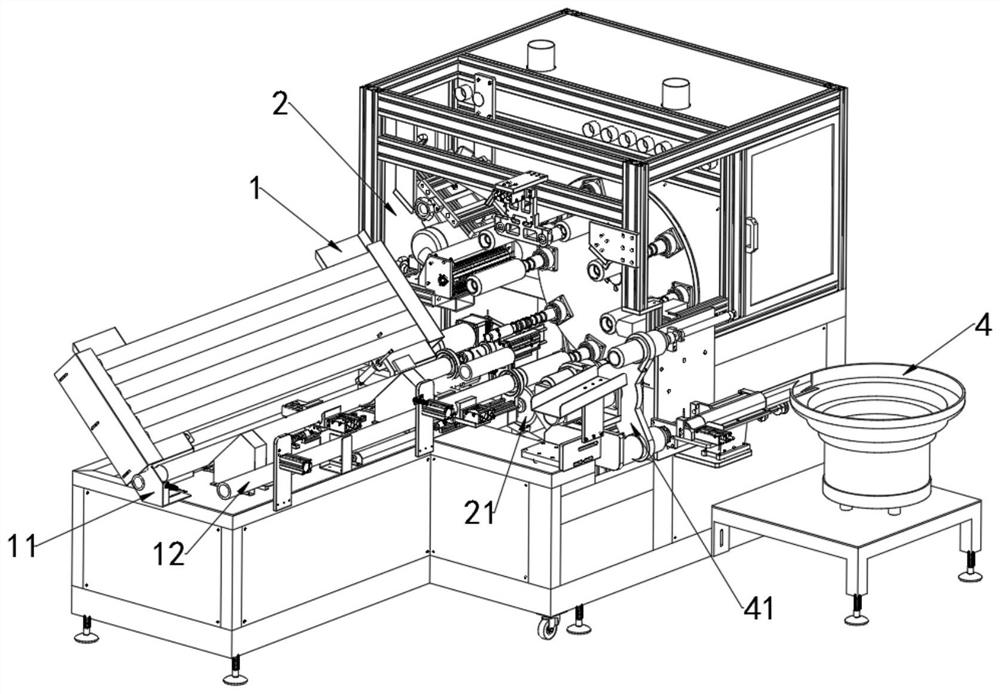

Image

  • Inner core mounting structure of roller bristle sleeve machine
  • Inner core mounting structure of roller bristle sleeve machine
  • Inner core mounting structure of roller bristle sleeve machine

Examples


Embodiment Construction

[0037] Embodiments of the present invention are described in detail below, examples of which are shown in the drawings, wherein the same or similar reference numerals designate the same or similar elements or elements having the same or similar functions throughout. The embodiments described below by referring to the figures are exemplary only for explaining the present invention and should not be construed as limiting the present invention.

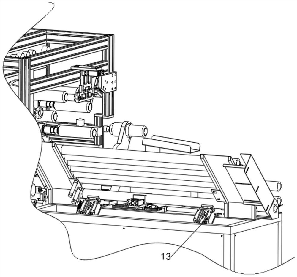
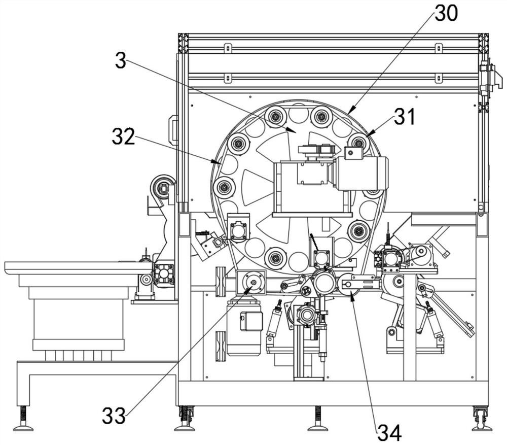
[0038] The invention discloses an inner core structure installed in a roller brush cover machine. The roller brush cover machine is mainly used for processing the cover rod of the roller brush. See Figure 1-18 , the roller brush cover machine includes a blanking mechanism 1, a cover processing area 2, a vertical first turntable 3 is arranged in the cover processing area, and a number of supporting shafts are evenly distributed on the circumference of the first turntable, and the turntable is a uniform step interval. Rotating, the first ...


PUM


Abstract

The invention discloses an inner core mounting structure of a roller bristle sleeve machine. The inner core mounting structure is characterized in that N supporting shafts are uniformly arranged on the circumference of a first rotary disc; a discharging mechanism conveys bristle sleeve rods to a first station supporting shaft of the first rotary disc; a first cutter cuts the bristle sleeve rods in a fixed length manner; a disc replacing device horizontally pushes bristle sleeves from the supporting shafts into sleeves of a second rotary disc; the second rotary disc is provided with a clamping station and an off-line station, and the second rotary disc is rotated to enable the bristle sleeves to complete clamping of inner cores; and a positioning plate is arranged on the front side of the clamping station, a vibration disc, a first core clamping groove and a second core clamping groove are arranged on the rear side of the clamping station, the first core clamping groove is connected with an inner core output rail of the vibration disc, displacement mechanisms are arranged beside the first core clamping groove and at the rear end of the second core clamping groove, the displacement mechanisms are used for enabling the inner cores to enter the second core clamping groove from the first core clamping groove and to be inserted into the bristle sleeves from the second core clamping groove, and the positioning plate is used for preventing the bristle sleeve from falling off from a cylinder sleeve. The structure is simple and effective and has low cost and compact and reasonable equipment layout.

Description

technical field [0001] The invention relates to the technical field of automatic processing equipment, and more specifically relates to a machine-installed inner core structure of a roller bristle sleeve. Background technique [0002] With the development of science and technology and the progress of processing technology, the degree of automation of production equipment is getting higher and higher. In the actual processing process of brush production, it is necessary to go through processes such as material cutting, one end nest, and inner core installation to manufacture roller sleeves. Finished products, although there are some special machines for the processing of this type of accessories, most of this type of equipment is designed for one or two processes. If the various processes are connected, then a larger site and a longer time are required production line. Therefore, the inventor of the present application puts a lot of energy into developing a kind of equipment...

Claims


Application Information

Patent Timeline
Patent Type & Authority Applications(China)
IPC IPC(8): A46D1/04A46D3/04A46D3/08
CPCA46D1/04A46D3/04A46D3/08A46D3/082
Inventor 李景照梁厚超李卫林枢檀
Owner SHUNDE POLYTECHNIC
Learn More