Garbage treatment device for building

A technology for garbage disposal and construction, applied in the direction of grain processing, etc., can solve the problems of increasing the time cost and labor cost of centralized garbage transportation, inconvenient moving and handling, and unfavorable recycling, so as to shorten the time cost and labor, and reduce the time cost. And the effect of high labor cost, crushing efficiency and utilization rate

Pending Publication Date: 2021-08-06
NORTHEAST FORESTRY UNIVERSITY
View PDF1 Cites 2 Cited by
  • Summary
  • Abstract
  • Description
  • Claims
  • Application Information

AI Technical Summary

Problems solved by technology

[0004] The construction waste treatment equipment in the prior art still has the following disadvantages in actual use: the construction waste treatment equipment has poor crushing effect on bricks, concrete blocks and other garbage, and the crushing is uneven, which is not conducive to later recycling. Backfilling of

Method used


Image

  • Garbage treatment device for building
  • Garbage treatment device for building
  • Garbage treatment device for building

Examples


Embodiment 1

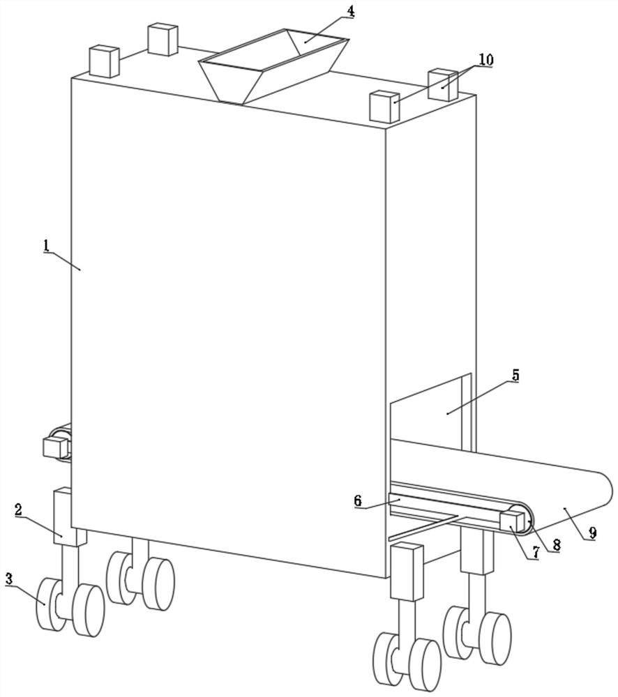
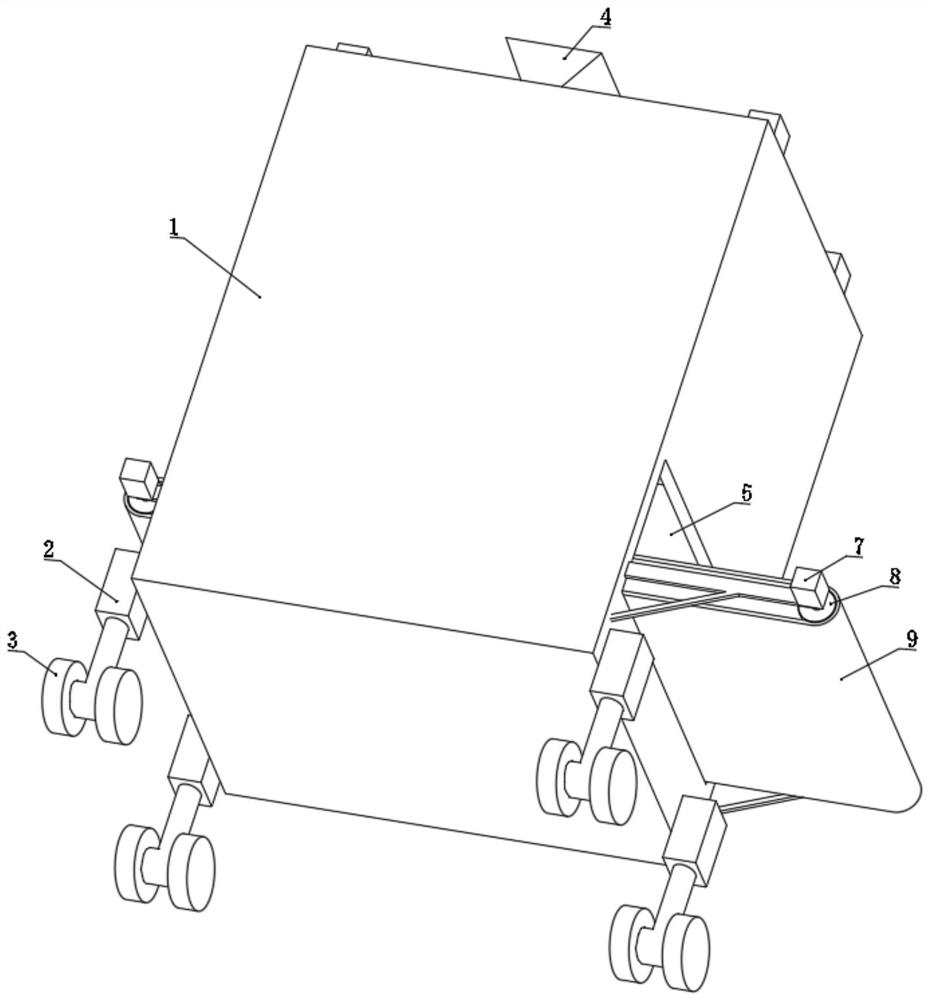
[0036] refer to Figure 1-4 , a construction waste treatment device, comprising a box body 1, a plurality of mounting seats 2 are installed on the bottom of the box body 1, and moving wheels 3 are installed on the bottom ends of the mounting seats 2, and the moving wheels 3 are four in total, and are symmetrical Distributed, the processing device of the present invention can realize convenient movement through four moving wheels 3, avoiding the time cost and labor, equipment and other costs caused by transporting garbage.

[0037] A hopper 4 is installed on the top wall of the box 1, and the bottom of the hopper 4 communicates with the inside of the box 1. Construction waste, such as bricks, concrete blocks, etc., is loaded from the hopper 4 to the box by excavators and other engineering equipment. within 1.

[0038] One side of the bottom of the box body 1 is provided with a side outlet 5, and the interior of the box body 1 is horizontally provided with a conveying mechanism...

Embodiment 2

[0049] When the crusher crushes bricks and concrete blocks, the crushed garbage and steel bars may be stuck between the crushing cones 15. Therefore, the second embodiment is based on the first embodiment above, and at the same time The following technical solutions are proposed:

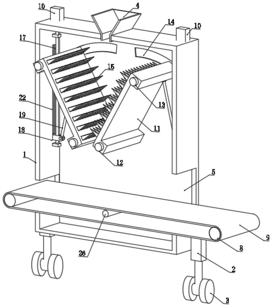
[0050] refer to Figure 5-9 , the inside of the box body 1 is vertically symmetrically installed with two separation plates 16 at a position between the two crushers, and the separation plates 16 are all fixed to the inner wall of the box body 1, and the two separation plates 16 are all fixed. A through hole 25 corresponding to the crushing cone 15 is opened through, a bottom outlet 23 is opened at the bottom of the box body 1 , and leak holes 24 are uniformly provided on the conveyor belt 9 .

[0051] The size of the through hole 25 provided on the separating plate 16 needs to ensure that the crushing cone 15 will not be affected when the rolling plate 11 swings.

[0052] Since the separation pla...


PUM


Abstract

The invention discloses a garbage treatment device for building, and belongs to the field of construction equipment. The garbage treatment device comprises a box body, a plurality of mounting seats are mounted at the bottom of the box body, moving wheels are mounted at the bottom ends of the mounting seats, a feeding hopper is mounted on the top wall of the box body, the bottom of the feeding hopper communicates with the interior of the box body, a side face outlet is formed in one side of the bottom of the box body, a conveying mechanism is transversely arranged inside the box body, the conveying mechanism comprises a first motor, a conveying roller and a conveying belt, a support is fixed to the outer side wall of the box body, and the conveying roller and the support are rotationally installed. According to the device, building garbage, especially bricks and concrete blocks, can be fully ground and crushed, the crushed garbage is more uniform, in addition, the crushed garbage and steel bars can be automatically separated and discharged, wast caused by incomplete separation of the steel bars is avoided, the situation that equipment components are clamped by the steel bars is also avoided, and therefore, the crushing efficiency and the utilization rate of the garbage are high.

Description

technical field [0001] The invention relates to the technical field of construction equipment, in particular to a construction waste treatment device. Background technique [0002] There is a lot of construction waste on the construction site. When dealing with construction waste, it needs to be crushed and then reused to save resources. [0003] After retrieval, Chinese Patent No. CN112675965A discloses a construction waste treatment device for construction engineering, including a shell, a feeding hopper is provided on the top of the shell, and a crushing mechanism for crushing construction waste is provided inside the shell , One side of the shell is provided with a water spray mechanism for settling the dust in the shell, and a separation mechanism is provided inside the shell, and the separation mechanism shakes in the vertical direction through the crushing mechanism. [0004] The construction waste treatment equipment in the prior art still has the following disadvan...

Claims


Application Information

Patent Timeline
IPC IPC(8): B02C1/04B02C1/10B02C21/02B02C23/00B02C23/10
CPCB02C1/043B02C1/10B02C21/02B02C23/00B02C23/10B02C2201/02
Inventor 马颖川武思好
Owner NORTHEAST FORESTRY UNIVERSITY
Why Eureka
Try Eureka