A gas treatment method and system based on a three-device refrigerant compression cycle

A gas treatment and refrigerant technology, applied in the functional system field, can solve the problems of easy condensation and large energy consumption, and achieve the effect of ensuring the heating effect, improving the energy efficiency of the system, and improving the system function.

Active Publication Date: 2022-05-10
湖南雅立科技开发有限公司
View PDF0 Cites 0 Cited by
  • Summary
  • Abstract
  • Description
  • Claims
  • Application Information

AI Technical Summary

Problems solved by technology

[0009] For refrigeration, at present, the temperature of the supply air cooled by the air conditioner evaporator is saturated air, which is prone to condensation, and some precision air conditioners use reheating to control the relative humidity of the supply air, but they often use electric heating, which consumes less energy. Big

Method used


Image

  • A gas treatment method and system based on a three-device refrigerant compression cycle
  • A gas treatment method and system based on a three-device refrigerant compression cycle
  • A gas treatment method and system based on a three-device refrigerant compression cycle

Examples


Embodiment 1

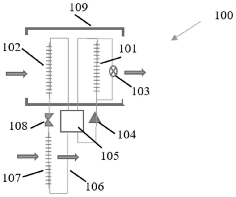
[0061] When the outdoor temperature is 0°C and the indoor air temperature is 20°C, the 100 system of the present invention (such as Figure 10 As shown) when heating indoor air (the compressor is Danfoss VZH035CJ, R410A, the evaporation temperature of the evaporator is -10°C, and the condensation temperature of the condenser is 45°C), the overall performance of the system is as follows:

[0062] 1. Total system heating, 19.8kW (10+5+2.4+2.4),

[0063] 2. Conventional system heating 15kW (10+5), of which, cooling 10kW, power consumption 5kW

[0064] 3. Add 2.4kW refrigeration for subcooling

[0065] 4. Add 2.4kW heating for subcooling

[0066] 5. Power consumption, 5kW

[0067] 6. COP, 3.96

[0068] Using conventional systems such as Figure 11 shown), when heating the indoor air (the compressor is Danfoss VZH044CJ, R410A, the evaporation temperature of the evaporator is -10°C, and the condensation temperature of the condenser is 45°C), the overall performance of the syste...

Embodiment 2

[0082] When the outdoor air is -10°C, adopt the 100 system of the present invention (such as Figure 10 As shown) when the fresh air is heated (the compressor is Danfoss VZH028CH, R410A, the evaporation temperature of the evaporator is -20°C, and the condensation temperature of the condenser is 45°C), the overall performance of the system is as follows:

[0083] 1. Heating, 14.8kW (5+3.8+3+3),

[0084] 2. Conventional system heating 8.8kW (5+3.8), cooling 5kW, power consumption 3.8kW

[0085] 3. Add 3kW refrigeration for subcooling

[0086] 4. Add 3kW heating for subcooling

[0087] 5. Power consumption, 3.8kW

[0088] 6. COP, 3.9

[0089] Using conventional systems such as Figure 13 shown), when heating the indoor air (the compressor is Danfoss DCJ106T2, R410A, the evaporation temperature of the evaporator is -20°C, and the condensation temperature of the condenser is 45°C), the overall performance of the system is as follows:

[0090] 1. Heating, 15.43kW

[0091] 2. ...


PUM


Abstract

The invention provides a gas treatment method and system based on three-device refrigerant circulation, the system includes a first gas heat exchanger, a second gas heat exchanger, an outdoor air heat exchanger, a compressor, a throttling mechanism, and a four-way valve Wait. Gas treatment includes heating, cooling and dehumidification. During heating, the gas passes through the first gas heat exchanger and the second gas heat exchanger to be heated by the refrigerant to achieve heating. The refrigerant circulation during heating includes the first heating cycle and the second heating cycle. Two heating cycles, four-way valve switching can realize evaporator defrosting while heating. During refrigeration, the gas passes through the first gas heat exchanger and the second gas heat exchanger in turn to be cooled by the refrigerant to realize refrigeration. During dehumidification, the gas is first cooled and dehumidified by the first gas heat exchanger, and then heated by the second gas heat exchanger to reduce the relative humidity. The invention can improve the energy efficiency of the system, ensure the heating effect and provide uninterrupted heat supply, etc., and can be used in various air-conditioning heat pump dehumidification systems, including commercial, civil and industrial occasions.

Description

technical field [0001] The invention relates to a system which utilizes the refrigerant compression cycle of three heat exchangers to realize the functions of gas heating, cooling and dehumidification. Background technique [0002] A conventional refrigerant compression cycle contains only two units, evaporator and condenser, and four processes, evaporation, compression, condensation and expansion. [0003] The process from evaporation to compression is reasonable. The low-temperature gas produced by evaporation is very suitable for being directly compressed into the compressor, because the compression power consumption of low-temperature cold gas is lower than that of high-temperature gas, but the process from condensation to expansion is unreasonable. Because the condensed refrigerant hot liquid also contains a lot of sensible heat, for refrigeration, the direct expansion and decompression of the hot fluid will offset the cooling capacity of the evaporator. [0004] For h...

Claims


Application Information

Patent Timeline
Patent Type & Authority Patents(China)
IPC IPC(8): F25B13/00F25B41/26F25B47/02
CPCF25B13/00F25B47/025
Inventor 袁一军叶立英
Owner 湖南雅立科技开发有限公司
Why Eureka
Try Eureka