Grating structure

A grating structure and grating technology, applied in diffraction gratings, optics, optical components, etc., can solve the problems of different dispersion capabilities, and achieve the effect of reducing the difficulty of process manufacturing, high extinction ratio and high efficiency polarization beam splitting function

Pending Publication Date: 2021-08-06
宁波舜宇奥来技术有限公司
View PDF0 Cites 3 Cited by
  • Summary
  • Abstract
  • Description
  • Claims
  • Application Information

AI Technical Summary

Problems solved by technology

[0004] The main purpose of the present invention is to provide a grating structure to solve the problem of different dispersion capabilities of ±1st-order diffracted light with different polarization states in the polarization beam splitting device in the prior art

Method used


Image

  • Grating structure
  • Grating structure
  • Grating structure

Examples


Embodiment 1

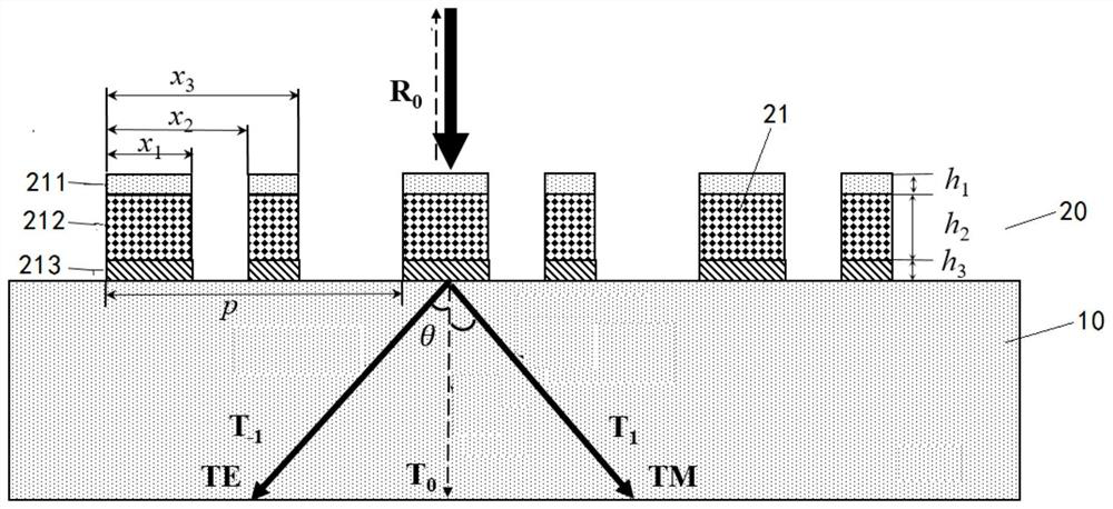
[0051] Such as figure 1 As shown, in this embodiment, the grating ridge 21 has a three-layer structure.

[0052] It should be noted that the wavelength is related to the parameters of the grating structure (according to the strict coupled wave theory, if the influence of the material refractive index change is not considered, the same diffraction efficiency value can be obtained by scaling the grating structure in proportion to the incident center wavelength) , such as when the incident center wavelength increases or decreases, the period of the grating structure and the depth of each layer also increase or decrease in proportion. But in reality, due to the influence of the material dispersion relationship on the different refractive indices corresponding to different wavelengths, the ratio of each parameter increase or decrease will be adjusted, but through proper optimization, more suitable grating parameters can also be found. Due to the difference in the optimization algor...

Embodiment 2

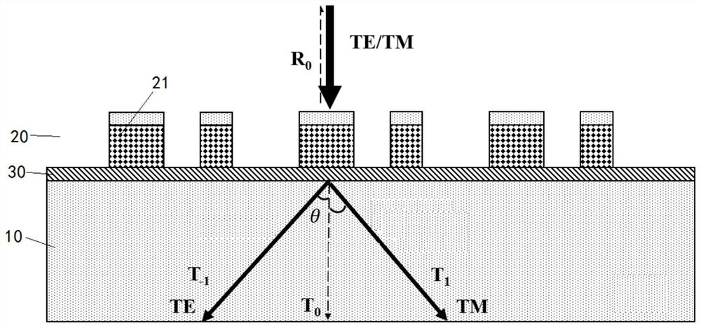
[0073] Such as figure 2 As shown, in this embodiment, the grating ridge 21 has two layers, and in this embodiment, there is a cut-off layer 30 between the grating layer 20 and the base structure 10, and the cut-off layer 30 may be a residual glue layer in the imprinting process , can also be a layer made separately. In this embodiment, the refractive index of the cut-off layer 30 is smaller than that of the layer connected to the cut-off layer 30 in the grating ridge 21 , and the refractive index of the cut-off layer 30 is greater than that of the base structure 10 . And the one of the two layers farther from the cut-off layer 30 has a smaller refractive index than the other layer.


PUM

PropertyMeasurementUnit
heightaaaaaaaaaa
heightaaaaaaaaaa
heightaaaaaaaaaa

Abstract

The invention provides a grating structure. The grating structure includes: a substrate structure; and a grating layer which is of a periodic structure, the grating in each period serves as a sub-grating, wherein the multiple sub-gratings are arranged on one side of the substrate structure at intervals, each sub-grating is of a rectangular structure and is of an asymmetric structure, and the period of the grating structure is smaller than 1.5 times of the incident center wavelength. The polarization beam splitter solves the problem that the dispersion capabilities of + / -1- level diffraction light in different polarization states are different in the polarization beam splitter in the prior art.

Description

technical field [0001] The present invention relates to the technical field of diffractive optical equipment, in particular to a grating structure. Background technique [0002] With the continuous development of future technology, polarizing beam splitters play an increasingly important role in optical systems. Especially in display fields such as AR (Augmented Reality), VR (Virtual Reality), and MR (Mixed Reality), in order to achieve 3D display effects, the left and right eyes need to observe different optical components to form a 3D observation experience. A polarizing beam splitter is usually required to allow left and right eyes to observe differently polarized light. However, most of the traditional polarizing beam splitter gratings are incident at the Littrow angle, so that the 0-order and -1-order diffracted light after diffraction by the grating present different polarization states. But for the optical waveguide system, this configuration has two disadvantages. ...

Claims


Application Information

Patent Timeline
Patent Type & Authority Applications(China)
IPC IPC(8): G02B5/18
CPCG02B5/1819
Inventor 尹正坤孙理斌汪杰陈远
Owner 宁波舜宇奥来技术有限公司
Why Eureka
Try Eureka