
Radiation shielding and thermal insulation device

A heat insulation device and radiation shielding technology, which is applied in the field of radiation shielding and heat insulation devices, can solve the problems of radioactive substance contamination, high radiation dose of operating personnel, burns, etc., and achieve the effect of solving high radiation dose

Active Publication Date: 2021-08-06
中广核工程有限公司 +3
View PDF13 Cites 0 Cited by
  • Summary
  • Abstract
  • Description
  • Claims
  • Application Information

AI Technical Summary

Problems solved by technology

In addition, when the welding machine equipment fails, it also needs close inspection and maintenance, and there is also the problem of high radiation dose of operating personnel
[0006] Since the transfer container is hoisted from underwater to the water surface, even after the surface is washed and decontaminated, α and β radioactive pollutants remain on the surface of the transfer container. When personnel operate at close range, it is difficult to avoid contamination and contamination of clothing and bodies by radioactive substances.
[0007] 2) Short-distance high-temperature burns
During the replacement of filling and drainage branch pipes, non-destructive testing, helium leakage monitoring, hydrogen monitoring, cleaning and decontamination, it is easy to cause burns
[0009] 3), personnel fall safety issues
[0014] Since the transport container is hoisted from underwater to the water surface, even after surface washing and decontamination, α and β radioactive pollutants remain on the surface of the transport container. It is difficult for personnel to avoid contamination of clothing and bodies by radioactive substances when operating at close range.
[0015] 2) Short-distance high-temperature burns
It is also easy to cause burns when personnel disassemble the filling and drainage pipelines, monitor helium leaks and clean and decontaminate

Method used


Image

  • Radiation shielding and thermal insulation device
  • Radiation shielding and thermal insulation device
  • Radiation shielding and thermal insulation device

Examples


Embodiment Construction

[0058] In order to have a clearer understanding of the technical features, purposes and effects of the present invention, the specific implementation manners of the present invention will now be described in detail with reference to the accompanying drawings.

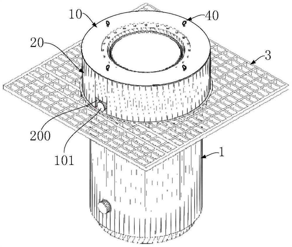
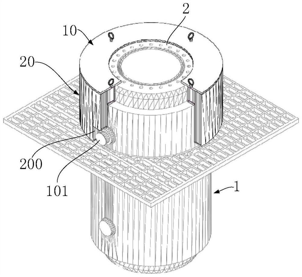
[0059] The radiation shielding and heat insulation device of the present invention is used to cover the upper end of the container to play the role of radiation protection and high temperature insulation; the container is a spent fuel transfer container or a spent fuel transport container.

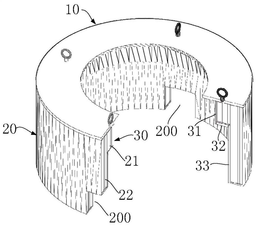
[0060] like Figure 1-Figure 3 As shown, the radiation shielding and heat insulation device of the first embodiment of the present invention may include an annular top plate 10, a shielding unit 20 and a heat insulation layer 30 connected below the annular top plate 10, and a plurality of suspension rings 40 arranged on the annular top plate 10 .

[0061] The annular top plate 10 is arranged corresponding to the outer circumference...


PUM


Abstract

The invention discloses a radiation shielding and thermal insulation device. The device comprises an annular top plate arranged on the top of the container in a matched mode, a shielding unit connected to the lower portion of the annular top plate, arranged on the periphery of the container in a surrounding mode and used for shielding neutrons and gamma rays, and a heat insulation layer arranged on the lower portion of the top plate and fixedly attached to the inner side of the shielding unit to wrap the periphery of the container. The radiation shielding and heat insulation device is used for covering the upper part of a spent fuel transfer container or a transport container, has radiation protection and high-temperature heat insulation functions, and solves the technical problems of high radiation dose / radioactive substance contamination, high operation temperature and the like during spent fuel loading operation.

Description

technical field [0001] The invention relates to the technical field of nuclear fuel protection, in particular to a radiation shielding and heat insulation device. Background technique [0002] The existing spent fuel dry storage container technology is mainly used for temporary storage of spent fuel. When carrying out the spent fuel loading operation, first hoist the empty spent fuel storage tank into the transfer container, then hoist the spent fuel assembly into the spent fuel storage tank under water, and then inflate and drain the spent fuel storage tank, store The tank cover is welded, vacuum-dried and filled with helium, and the spent fuel assembly is welded and sealed in the spent fuel storage tank. The existing spent fuel dry storage container technology has the following problems in the vacuum drying and welding operations during the spent fuel loading process: [0003] 1) Personnel radiation protection issues [0004] The vacuuming and drying operation of spent ...

Claims


Application Information

Patent Timeline
Patent Type & Authority Applications(China)
IPC IPC(8): G21F5/015G21F5/06G21F5/12
CPCG21F5/12G21F5/06G21F5/015Y02E30/30
Inventor 程呈戈永军潘跃龙唐邵华张学岭莫怀森杨寿海黄礼明唐琼辉王傲松魏志国张文利周智慧李仕元
Owner 中广核工程有限公司
Learn More