Modified organic silicon coating preparation equipment

An organosilicon coating and modification technology, applied in the field of coatings, can solve the problems of reducing the reaction rate, increasing the cost of the enterprise, time-consuming and laborious, etc., and achieving the effect of increasing the reaction rate, improving the quality of the product, and improving the quality of the product.

Inactive Publication Date: 2021-08-10
付豪
View PDF11 Cites 0 Cited by
  • Summary
  • Abstract
  • Description
  • Claims
  • Application Information

AI Technical Summary

Problems solved by technology

[0004] In order to make up for the deficiencies of the existing technology, the solution is that the reaction solution is only dispersed by the stirring device in the prior art, the raw materials at the bottom of the reactor cannot be stirred, the raw materials are poor in discreteness, easy to precipitate, there are incompletely dissolved particles, and even form agglomerates It is difficult to clean up the material accumulated on the inner wall of the bottom of the reactor, which reduces the reaction rate; and in the prior art, feeding is usually done manually or by setting a conveying device, which is time-consuming and labor-intensive, resulting in a waste of human resources; the power source of the conveying device consumes a lot of energy. Increase the cost of the enterprise, which is not conducive to the large-scale production of the factory. The present invention proposes a modified silicone coating preparation equipment

Method used


Image

  • Modified organic silicon coating preparation equipment
  • Modified organic silicon coating preparation equipment

Examples


Embodiment approach

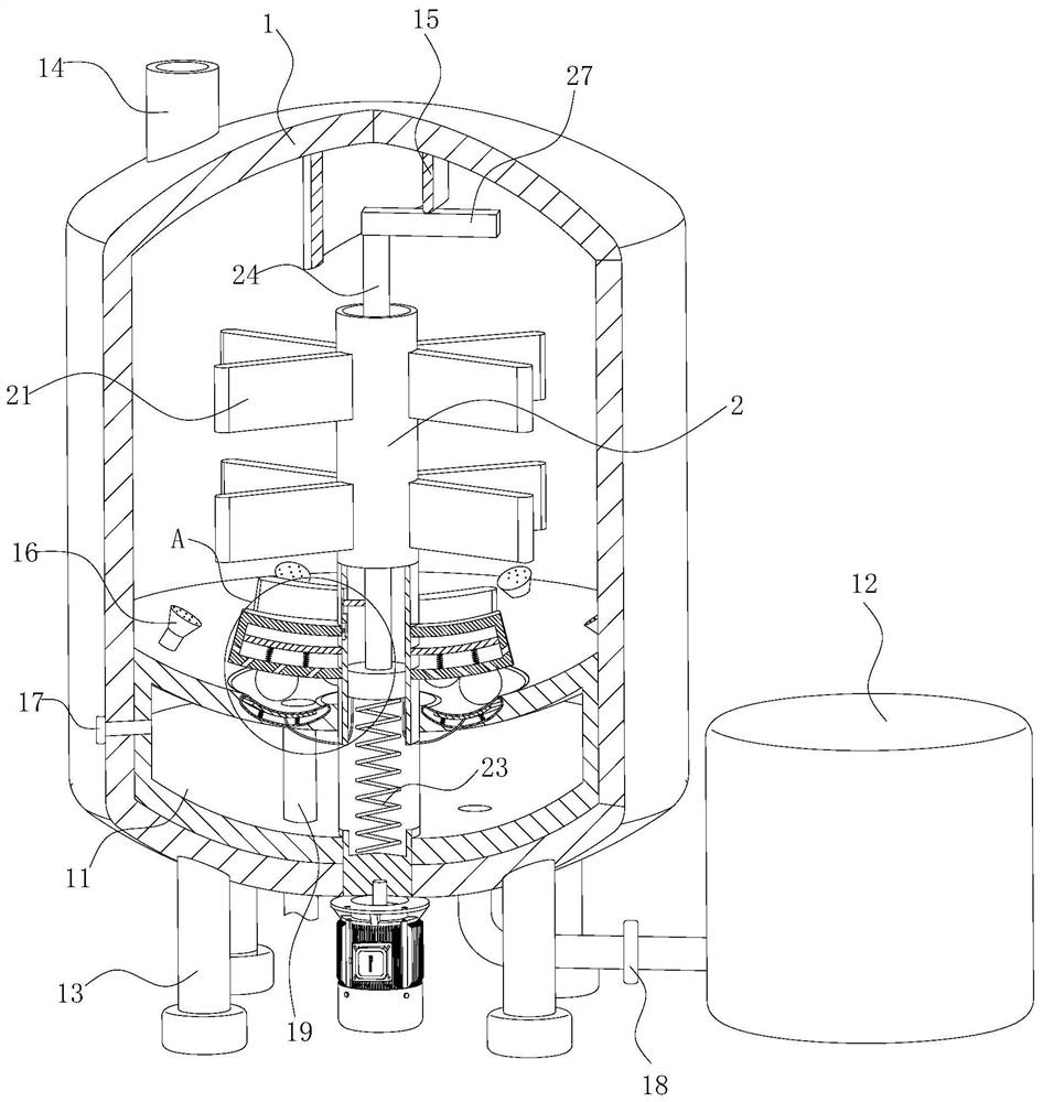
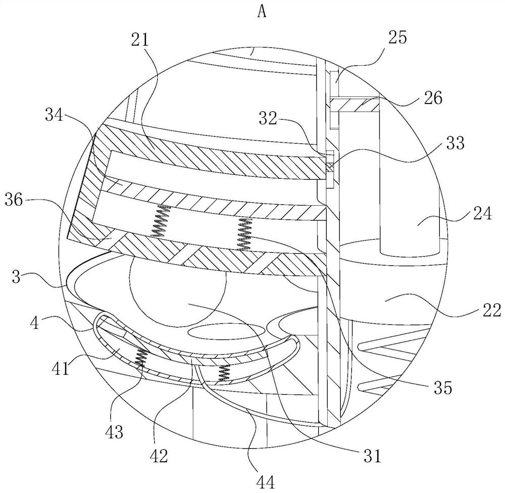
[0025] As an embodiment of the present invention, the surface of the rotating shaft 2 is provided with evenly distributed second clamping grooves 32, the second clamping grooves 32 are arranged in one-to-one correspondence with the bottom group of stirring rods 21, and the bottom group of stirring rods 21 are fixedly connected with a second clamping block 33, and the second clamping block 33 is connected to the second clamping groove 32 by sliding up and down; the bottom group of stirring rods 21 are designed with a hollow structure inside, and the bottom group of stirring rods 21 is sealed and slidingly connected with a fixed plate 34, one end of the fixed plate 34 is fixedly connected with the rotating shaft 2, and a uniformly arranged second spring 35 is fixedly connected between the fixed plate 34 and the inner wall of the bottom group of stirring rods 21 When working, the liquid moving in the reaction kettle 1 impacts the stirring rod 21, so that the lowermost group of sti...


PUM


Abstract

The invention belongs to the technical field of coatings, and particularly relates to modified organic silicon coating preparation equipment. The equipment comprises a reaction kettle, a liquid inlet bin and a storage tank; a fixed cylinder is fixedly connected to the center of the inner wall of the top of the reaction kettle, a rotating shaft is rotatably connected to the center of the reaction kettle, and stirring rods which are uniformly arranged are fixedly connected to the outer surface of the rotating shaft; a piston plate is slidably connected into the rotating shaft in a sealed mode, a first spring is fixedly connected to the side face of one side of the piston plate and the inner wall of the rotating shaft, a connecting rod is fixedly connected to the side face of the other side of the piston plate, and a horizontally-placed rotating rod is fixedly connected to the upper end of the connecting rod; a liquid inlet bin is arranged on the inner wall of the bottom of the reaction kettle, and spraying heads are uniformly arranged on the upper surface of the liquid inlet bin. According to the invention, the automatic liquid feeding and spraying of the liquid feeding bin can be achieved, energy consumption is reduced, and the production cost is reduced; meanwhile, the spraying head sprays liquid from different directions, so that the liquid in the reaction kettle is uniformly mixed, the liquid on the upper surface of the liquid inlet bin is impacted to accelerate liquid flowing, and materials are prevented from being deposited and attached to the inner wall of the reaction device.

Description

technical field [0001] The invention belongs to the technical field of coatings, in particular to equipment for preparing modified silicone coatings. Background technique [0002] Silicone resin coating is a kind of elemental organic coating with silicone resin or modified silicone resin as the main film-forming substance, referred to as silicone coating. Elemental organic coatings are a general term for coatings with elemental organic polymers as the main film-forming substance, including organic silicon, organic titanium, organic fluorine, organic aluminum, and organic zirconium coatings. Among them, silicone resin coatings have the largest output, and have special thermal stability, insulation, high temperature resistance, chemical resistance, water resistance, weather resistance, etc., and are widely used in defense industry, electrical industry and other industries. Although silicone resin has many characteristics, it also has many disadvantages: generally, high temper...

Claims


Application Information

Patent Timeline
IPC IPC(8): B01J19/00B01J19/26B02C15/14B02C19/16
CPCB01J19/26B01J19/0053B02C15/14B02C19/16
Inventor 付豪方舟
Owner 付豪
Why Eureka
Try Eureka