Device for controlling DPF carbon-supported capture and passive regeneration and control method

A passive regeneration and DPF technology, which is applied to the electronic control of exhaust treatment devices, mufflers, exhaust devices, etc., can solve the problems of engine oil dilution, engine combustion deterioration, oil viscosity drop, etc., and achieves high temperature controllability. , The effect of less pollution and rapid temperature rise

Active Publication Date: 2021-08-10
WUXI WEIFU LIDA CATALYTIC CONVERTER
View PDF2 Cites 5 Cited by
  • Summary
  • Abstract
  • Description
  • Claims
  • Application Information

AI Technical Summary

Problems solved by technology

[0005] 1. Fuel burns in DOC, and the temperature is high. If the control is unreasonable, or the engine fails suddenly, it may cause the internal structure of DPF to be ablated and lose the ability to capture PM;
[0006] 2. During the DPF regeneration process, the surface temperature of the entire post-processing carrier is also very high, which may burn or damage the wiring harness and sensors arranged on the post-processing surface;
[0007] 3. During the DPF regeneration process, most small and medium-displacement engines use post-injection technology in the cylinder, which will dilute the engine oil, reduce the viscosity of the oil, and reduce the lubricating ability;
[0008] 4. During the DPF regeneration process, the combustion of the engine deteriorates, and a large amount of pollutants are discharged into the atmosphere, causing pollution to the environment

Method used


Image

  • Device for controlling DPF carbon-supported capture and passive regeneration and control method
  • Device for controlling DPF carbon-supported capture and passive regeneration and control method
  • Device for controlling DPF carbon-supported capture and passive regeneration and control method

Examples


Embodiment Construction

[0060] The following will clearly and completely describe the technical solutions in the embodiments of the present invention. Obviously, the described embodiments are only some of the embodiments of the present invention, rather than all the embodiments. Based on the embodiments of the present invention, all other embodiments obtained by persons of ordinary skill in the art without making creative efforts belong to the protection scope of the present invention.

[0061] The present invention will be further described below in conjunction with specific embodiments and accompanying drawings. It should be understood that the specific embodiments described here are only used to illustrate and explain the present invention, and are not intended to limit the present invention. The present invention will be further described below in conjunction with the accompanying drawings and embodiments.

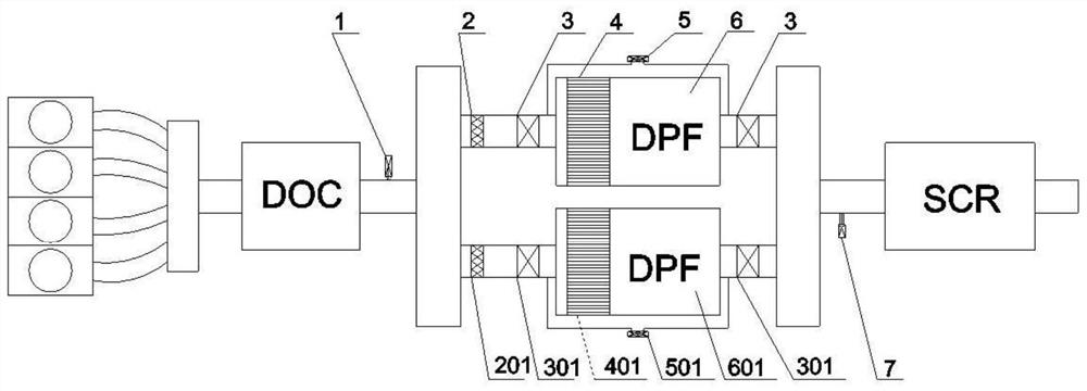
[0062] An embodiment of the present invention provides a device for controlling DPF carb...


PUM


Abstract

The invention discloses a device for controlling DPF(diesel particulate filter)carbon-loaded capture and passive regeneration and a control method. The device comprises a NOx sensor, a DPF parallel assembly and a temperature sensor, wherein the NOx sensor is located on an upstream pipeline of the DPF parallel assembly, and the temperature sensor is located on a downstream pipeline of the DPF parallel assembly. The DPF parallel assembly comprises at least two sets of DPF pipelines arranged in parallel, each DPF pipeline comprises a DPF carrier, an air flow meter, a one-way valve, a differential pressure sensor and a resistance wire, and the resistance wire is located at the front end of each DPF carrier. By comparing each real-time measured numerical value with a threshold value set by the system, the one-way valves are controlled to switch waste gas to flow between the DPF carriers, and the resistance wires are controlled to start / stop heating. According to the carbon loading amount of each DPF, the flowing of waste gas among different DPFs is switched through the one-way valves, the DPFs are actively regenerated through the resistance wires, and the device has the advantages that the temperature controllability is high, the temperature rise is fast, and the over-temperature phenomenon is few.

Description

technical field [0001] The invention belongs to the technical field, and in particular relates to a device and a control method for controlling DPF carbon load capture and passive regeneration. Background technique [0002] Automobile exhaust emission standards are becoming more and more stringent, especially with the implementation of the National VI emission regulations for light vehicles. Whether it is a diesel engine or a gasoline engine, the requirements for particulate matter in the National VI Standard are much stricter than the National V Standard (gasoline engines are tightened by more than 30%) , all particles must be filtered to meet emission regulations. [0003] At present, the mainstream technical solution of diesel engine's National VI post-treatment is the diesel oxidation catalyst DOC+gasoline particulate filter DPF+selective catalytic reduction SCR route. When the amount of PM in the DPF reaches the maximum limit that the DPF can withstand, the PM in the D...

Claims


Application Information

Patent Timeline
IPC IPC(8): F01N9/00F01N11/00F01N3/027F01N13/00
CPCF01N9/002F01N11/00F01N11/002F01N11/007F01N3/027F01N13/011Y02T10/40
Inventor 卢丰翥
Owner WUXI WEIFU LIDA CATALYTIC CONVERTER
Why Eureka
Try Eureka