
Superconducting magnetic suspension bearing mechanism

A magnetic suspension bearing and superconducting technology, applied in the direction of bearings, shafts and bearings, mechanical equipment, etc., can solve the problems of high cost and complex structure, and achieve the effects of high uniformity, large movable space and high self-stability

Pending Publication Date: 2021-08-10
TIANJIN UNIV
View PDF9 Cites 0 Cited by
  • Summary
  • Abstract
  • Description
  • Claims
  • Application Information

AI Technical Summary

Problems solved by technology

[0006] The purpose of the present invention is to overcome the deficiencies in the prior art, and propose a superconducting magnetic suspension bearing mechanism based on the principle of electromagnetic induction between the superconducting closed loop and the permanent magnet, which can solve the problem of the existing superconducting magnetic suspension bearings with uniform texture. The dependence of superconducting blocks and other problems can make up for the shortcomings of the existing superconducting magnetic suspension bearings, such as high cost and complex structure, and has the advantages of higher stability and axial tolerance.

Method used


Image

  • Superconducting magnetic suspension bearing mechanism
  • Superconducting magnetic suspension bearing mechanism
  • Superconducting magnetic suspension bearing mechanism

Examples


Embodiment 1

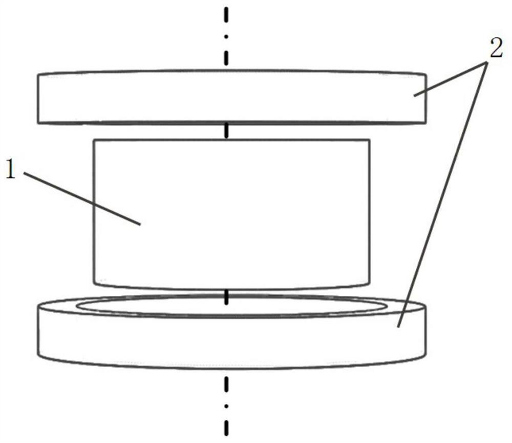
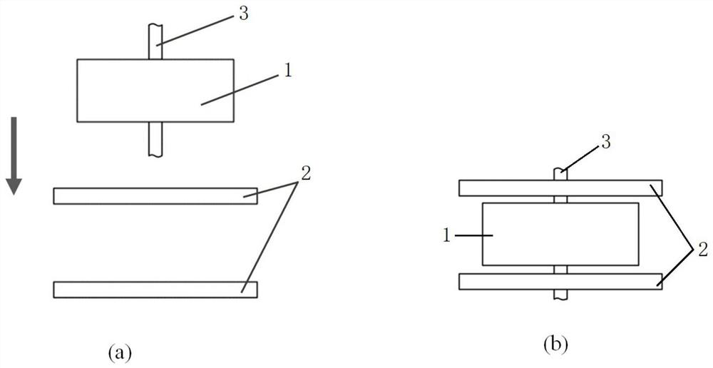
[0037] This embodiment provides a vertical superconducting magnetic suspension bearing mechanism, the schematic diagram is as follows figure 2 shown. The mechanism includes: a permanent magnet 1 , a superconducting closed winding 2 and a main shaft 3 .

[0038]The connection relationship and functions among the above components are as follows: the permanent magnet 1 and the superconducting closed winding 2 are arranged coaxially. The superconducting closed winding 2 adopts a jointless superconducting coil, which is symmetrically placed on the upper and lower ends of the permanent magnet 1 relative to the permanent magnet 1 and rigidly fixed on the suspension system bracket respectively. The geometric center distance between the two jointless superconducting coils is equal to 1.5 times the sum of the height of the permanent magnet 1 and the height of a single jointless superconducting coil. The jointless superconducting coil at the upper end of the permanent magnet 1 is used...

Embodiment 2

[0042] This embodiment provides a horizontal five-degree-of-freedom superconducting magnetic suspension bearing mechanism, the schematic diagram is as follows image 3 shown. The mechanism includes: a permanent magnet 1 , a superconducting closed winding 2 , a main shaft 3 and a permanent magnet ring 4 .

[0043] The connection relationship and functions among the above components are as follows: the permanent magnet 1 and the superconducting closed winding 2 are arranged coaxially. The superconducting closed winding 2 adopts a jointless superconducting coil, which is symmetrically placed on the left and right sides of the permanent magnet 1 relative to the permanent magnet 1, and can be controlled to move along the axis according to requirements. The jointless superconducting coil on the left side of the permanent magnet 1 is used to provide the permanent magnet 1 with a force to the right along the axis, and the jointless superconducting coil on the right side of the perman...


PUM


Abstract

The invention discloses a superconducting magnetic suspension bearing mechanism. The mechanism is composed of a permanent magnet and two identical superconducting closed windings which are arranged along a coaxial line, and the two superconducting closed windings are symmetrically arranged on two sides of the permanent magnet; in addition, a permanent magnet ring coaxially arranged can be connected with the exterior the permanent magnet in a sleeving mode, the permanent magnet and the permanent magnet ring are not contacted, and the magnetization direction is the same as that of the permanent magnet; and when in use, the two superconducting closed windings and the permanent magnet ring are rigidly fixed on a suspension system bracket respectively, and the permanent magnet is coaxially connected with a working rotor supported by the permanent magnet. The mechanism can be applied to the fields of flywheel energy storage and the like, and operation loss caused by mechanical friction is reduced.

Description

technical field [0001] The present invention relates to a brand-new theoretical bearing technology, and more specifically, relates to a superconducting magnetic suspension bearing mechanism. Background technique [0002] Flywheel energy storage has high efficiency (up to 90%), large instantaneous power (single megawatt level), fast response speed (several milliseconds), long service life (100,000 cycles and more than 15 years), and low environmental impact. It is one of the most promising short-term high-power energy storage technologies at present. The bearings used in flywheel energy storage usually include rolling bearings, hydrodynamic bearings, magnetic suspension bearings, etc. The loss generated by the bearing has a great contribution to the loss of the flywheel energy storage system. Therefore, improving the working reliability of the bearing suitable for flywheel energy storage, reducing its operation loss and prolonging its service life are the main research direc...

Claims


Application Information

Patent Timeline
IPC IPC(8): F16C32/04
CPCF16C32/0461F16C32/0465F16C32/0468F16C32/0489F16C2361/55
Inventor 信赢熊佳玲杨天慧李文鑫
Owner TIANJIN UNIV
Learn More