Built-in single-section circulating multilayer drying kiln

A built-in, drying kiln technology, applied in the kiln field, can solve problems such as energy saving, dark cracks, and heat waste, and achieve the effects of avoiding heat loss, increasing heat supply, and reducing moisture discharge

Pending Publication Date: 2021-08-10
FOSHAN JINBAILI ELECTROMECHANICAL
View PDF0 Cites 1 Cited by
  • Summary
  • Abstract
  • Description
  • Claims
  • Application Information

AI Technical Summary

Problems solved by technology

Affected by the rise of hot air, the fall of cold air and the loss of heat energy, the temperature of the transverse section of each layer of the kiln is not consistent, and there is a large temperature difference, which is prone to brick cracks or dark cracks, resulting in product loss and quality degradation; and the existing drying kiln Part of the heat in the kiln is directly pumped out with the moisture, and the remaining heat in the moisture cannot be recycled, and part of it is directly transferred to the atmosphere through the kiln body, resulting in waste of heat energy, which does not meet the concept of energy saving and consumption reduction.

Method used


Image

  • Built-in single-section circulating multilayer drying kiln
  • Built-in single-section circulating multilayer drying kiln
  • Built-in single-section circulating multilayer drying kiln

Examples


Embodiment Construction

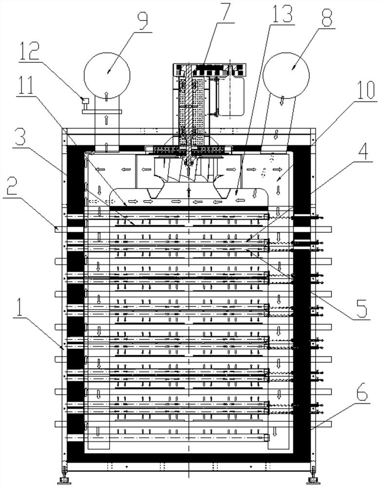
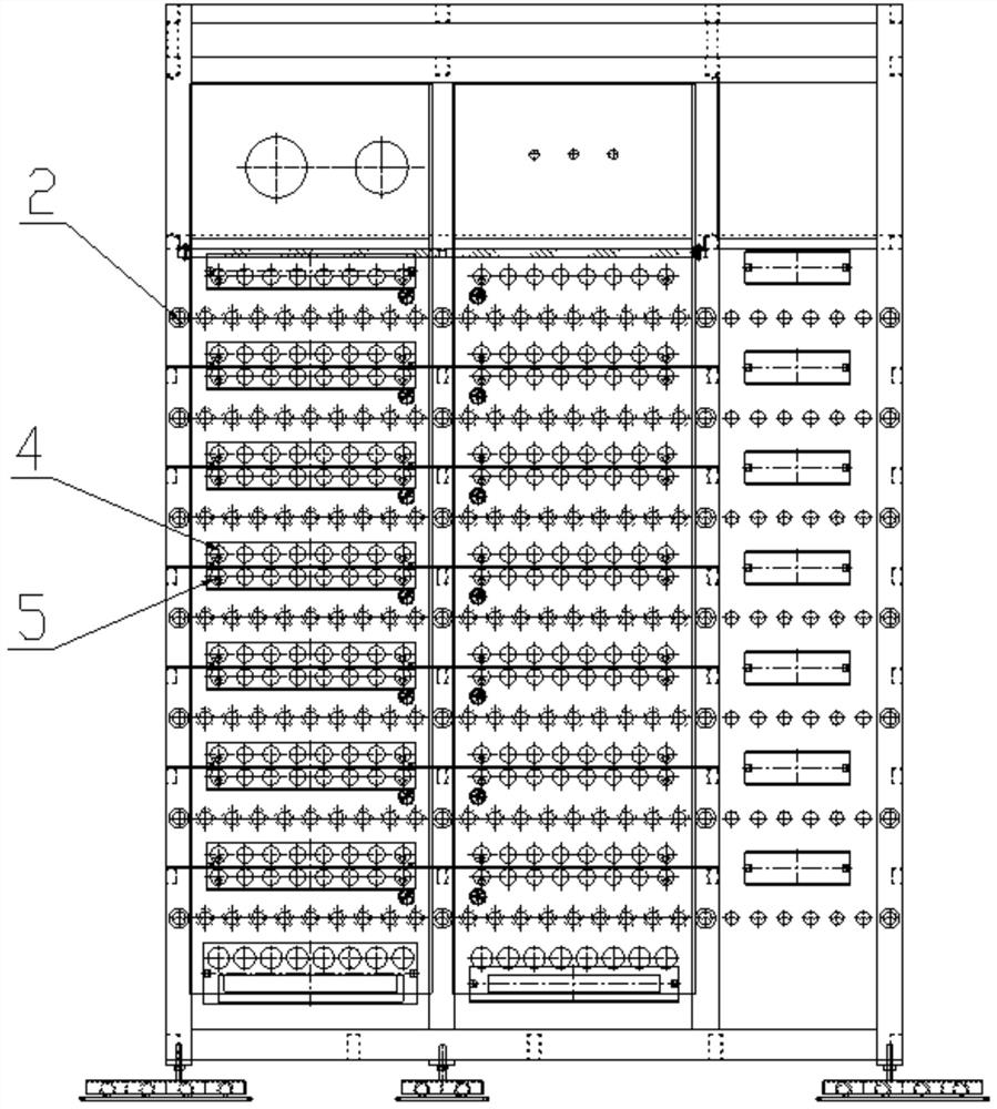
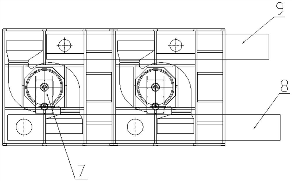
[0021] The present invention is described in further detail now in conjunction with accompanying drawing. These drawings are all simplified schematic diagrams, which only illustrate the basic structure of the present invention in a schematic manner, so they only show the configurations related to the present invention.

[0022] In the present invention, it should be noted that the orientations or positional relationships indicated by the terms "upper (top)", "lower (bottom)", "inner", "outer", and "between" are based on the The orientation or positional relationship is only for the convenience of describing the present invention and simplifying the description, but does not indicate or imply that the device or element referred to must have a specific orientation, be constructed and operated in a specific orientation, and therefore cannot be construed as limiting the present invention ; The term "several" means that the number is not less than 10, and this term is used for desc...


PUM


Abstract

The invention discloses a built-in single-section circulating multilayer drying kiln. The built-in single-section circulating multilayer drying kiln comprises a kiln body, a heat supply main pipe and a moisture removal main pipe, wherein the inner side wall of the kiln body is covered with a heat preservation layer, a plurality of conveying rollers are arranged in the kiln body, a heat supply lower branch pipe and a heat supply upper branch pipe are arranged on and below each conveying roller correspondingly, a bidirectional draught fan is installed at the top of the kiln body, an air outlet of the draught fan is formed inside the kiln body and is connected to a heat supply side pipe extending to the side wall of the kiln body, the heat supply lower branch pipe and the heat supply upper branch pipe are both connected to the heat supply side pipe, a heat preservation partition plate is further arranged in the kiln body, a partition space is formed between the heat preservation partition plate and the upper wall of the kiln body, and an air inlet of the draught fan is formed in the partition space. According to the built-in single-section circulating multilayer drying kiln, ceramic tiles on the conveying rollers can be quickly dried, meanwhile, it can be guaranteed that the temperature of the transverse section of the kiln is consistent, moisture heat energy can be further released again after moisture matches with heat supply gas to be sucked into the draught fan, and the heat preservation effect of the heat preservation layer match, so that the purposes of saving energy and reducing consumption are achieved.

Description

technical field [0001] The invention relates to the technical field of kilns, in particular to a built-in single-section circulation multi-layer drying kiln. Background technique [0002] At present, most of the drying kilns for ceramic production are five-layer drying kilns. The heating pipe enters from the top of the drying kiln and supplies heat to each layer in turn. Affected by the rise of hot air, the fall of cold air and the loss of heat energy, the temperature of the transverse section of each layer of the kiln is not consistent, and there is a large temperature difference, which is prone to brick cracks or dark cracks, resulting in product loss and quality degradation; and the existing drying kiln Part of the heat in the kiln is directly pumped out with the moisture, and the remaining heat in the moisture cannot be recycled, and part of it is directly transmitted to the atmosphere through the kiln body, resulting in waste of heat energy, which does not meet the conc...

Claims


Application Information

Patent Timeline
Patent Type & Authority Applications(China)
IPC IPC(8): F26B15/12F26B21/00F26B21/08F26B21/10F26B23/10F26B25/00
CPCF26B15/122F26B21/004F26B21/08F26B21/10F26B23/10F26B25/004F26B2210/02
Inventor 丁国友
Owner FOSHAN JINBAILI ELECTROMECHANICAL
Why Eureka
Try Eureka