

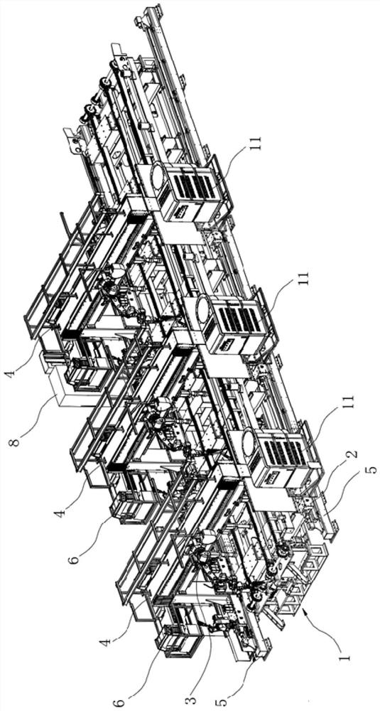
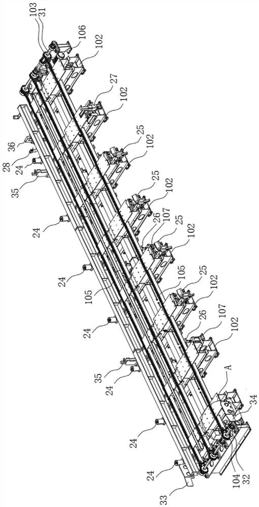
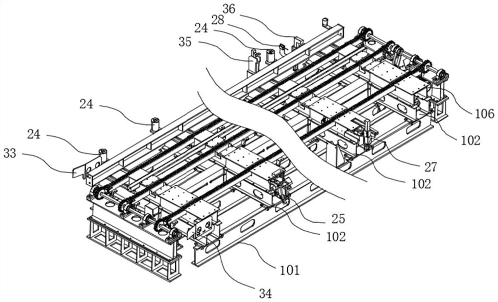
Automatic welding production line
An automatic welding and production line technology, applied in welding equipment, welding equipment, auxiliary welding equipment, etc., can solve the problems of poor dimensional accuracy and consistency, large randomness, and low degree of automation, and achieve the effect of welding gap and accurate welding.
- Summary
- Abstract
- Description
- Claims
- Application Information
AI Technical Summary
Problems solved by technology
Method used
Image

Examples
Embodiment Construction
[0028] The specific implementation manners of the present invention will be further described in detail below in conjunction with the accompanying drawings and embodiments. The following examples are used to illustrate the present invention, but are not intended to limit the scope of the present invention.
[0029] In the description of the present invention, it should be noted that unless otherwise specified and limited, the terms "installation", "connection", "connection" and "communication" should be understood in a broad sense, for example, it can be a fixed connection, or It can be a detachable connection or an integral connection; it can be a mechanical connection or an electrical connection; it can be a direct connection or an indirect connection through an intermediary, and it can be the internal communication of two components. Those of ordinary skill in the art can understand the specific meanings of the above terms in the present invention in specific situations.
...
PUM
 Abstract
Description
Claims
Application Information