Air supercharging main machine with combined air valves
A combined air valve and air pressurization technology, applied in the direction of mechanical equipment, machines/engines, liquid variable capacity machinery, etc., can solve the problems of unfavorable piston cylinder maintenance and repair, achieve good sealing effect, improve sealing performance, and improve operation The effect of working conditions
- Summary
- Abstract
- Description
- Claims
- Application Information
AI Technical Summary
Problems solved by technology
Method used
Image

Examples
Embodiment 1
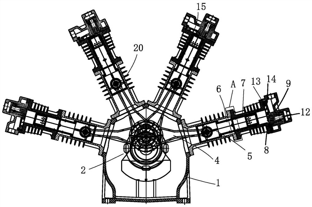
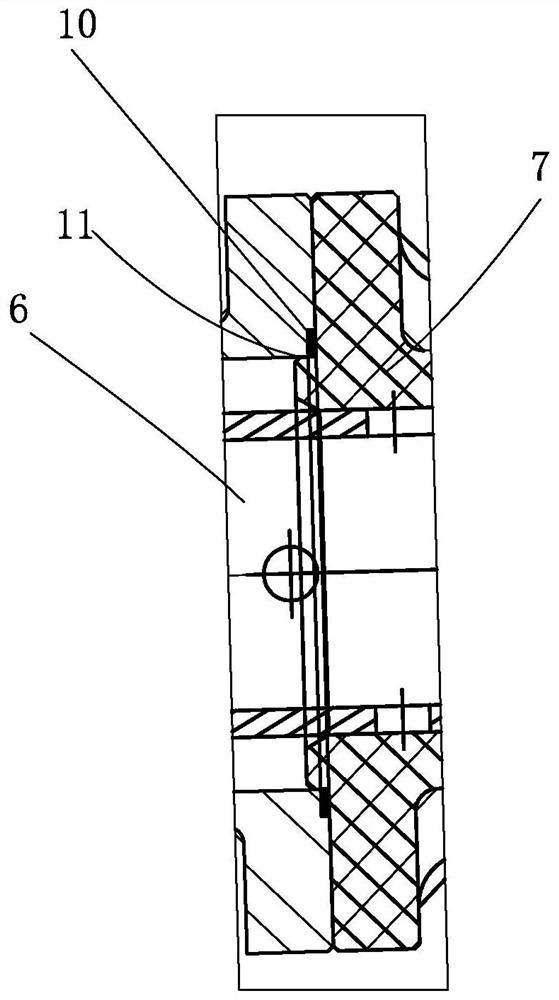
[0023] Such as figure 1 As shown, the present invention discloses an air booster main engine with a combined air valve, including a main engine base 1, a crankshaft unit 2 is installed in the main engine base 1, and one end of the crankshaft unit 2 is connected with a drive shaft protruding from the main engine base. 1 The transmission shaft outside the casing, one end of the crankshaft unit 2 is rotationally connected to one end of several connecting rods 4, the other end of the connecting rod 4 is connected to a piston 5, and the top of the main engine base 1 is installed with several pistons that cooperate with the piston 5 Cylinder unit, the piston unit includes a first piston cylinder 6, a second piston cylinder 7, a combined air valve 8 and a cylinder cover 9, the bottom of the first piston cylinder 6 is connected to the base 1 of the main engine, and the inner edge of the top of the first piston cylinder 6 A groove is provided, and a sealing ring 10 is installed in the ...
Embodiment 2
[0026] Such as Figure 1-5 As shown, the present invention discloses an air booster main engine with a combined air valve, including a main engine base 1, a crankshaft unit 2 is installed in the main engine base 1, and one end of the crankshaft unit 2 is connected with a drive shaft protruding from the main engine base. 1 The transmission shaft 3 outside the casing, one end of the crankshaft unit 2 is rotationally connected with one end of several connecting rods 4, the other end of the connecting rod 4 is connected with a piston 5, and the top of the main engine base 1 is installed with several pistons that cooperate with the piston 5 The piston cylinder unit is characterized in that: the piston unit includes a first piston cylinder 6, a second piston cylinder 7, a combined air valve 8 and a cylinder cover 9, the bottom of the first piston cylinder 6 is connected with the main engine base 1, and the first piston cylinder The inner edge of the top of 6 is provided with a groov...
Embodiment 3
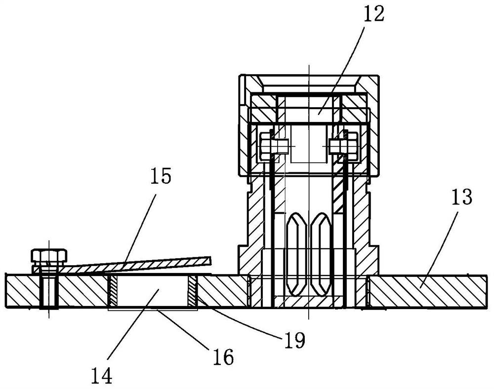
[0027] Embodiment 3: On the basis of Embodiment 2, the vent hole 14 is provided with a valve 16 for one-way ventilation. The valve 16 is cracked with several arc-shaped cracks 17 from the center to the periphery, and the edge of the valve 16 extends upwards. Install the membrane 18, as shown in the figure, the air can be discharged from the slit 17 as shown by the arrow of the one-way discharge of the airflow. When the function of closing the exhaust hole when the control valve plate contacts the installation plate fails, the air cannot pass through the one-way valve 16, which means The valve 16 assumes the function of closing the exhaust hole in the second stage.
[0028] The hole wall of the exhaust hole 14 is provided with an external thread, and an installation ring 19 cooperating with the external thread is also installed on the exhaust hole 14. The installation film 18 is fixedly connected between the installation ring 19 and the external thread, and the installation is f...
PUM
 Abstract
Description
Claims
Application Information
PatSnap Eureka turns technology decisions into work you can execute. Powered by our Innovation Knowledge Graph, it runs expert workflows across engineering, life sciences, materials and intellectual property. Get your review-ready output in minutes.


