A common anode diode device and its preparation method

A diode and common anode technology, which is applied in the field of common anode diode devices and its preparation, can solve the problems that the diode cathode cannot be directly connected to, poor current carrying capacity, and poor heat dissipation of the product, so as to reduce the number of uses and improve the surge capacity , Improve the effect of heat dissipation

Active Publication Date: 2022-04-22
瑞能微恩半导体(上海)有限公司
View PDF12 Cites 0 Cited by
  • Summary
  • Abstract
  • Description
  • Claims
  • Application Information

AI Technical Summary

Problems solved by technology

[0004] Because the heat dissipation of the diode chip is mainly through the cathode, but in the current packaging method, the cathode of the diode cannot be directly connected to the copper heat sink or can only be directly connected to a part of the copper heat sink, resulting in poor heat dissipation of the product, and in the current packaging method, the diode The anode achieves diode conduction through aluminum wire welding or a copper connection piece with a small contact area, and the current carrying capacity is poor, resulting in poor surge capacity

Method used


Image

  • A common anode diode device and its preparation method
  • A common anode diode device and its preparation method
  • A common anode diode device and its preparation method

Examples


Embodiment 1

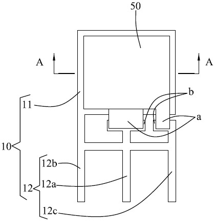
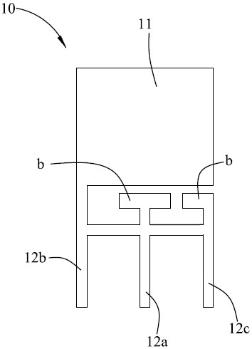
[0051] see Figure 1-Figure 7 , shows the common anode diode device in Embodiment 1 of the present invention, including a conductive support 10, a first diode chip 20, an anode copper sheet 30, a second diode chip 40 and a cathode copper sheet 50, wherein:

[0052] The conductive bracket 10 includes a heat sink 11 and at least two pins 12 arranged on one side of the heat sink 11, and the first diode chip 20 is welded on the heat sink 11 in a way that the cathode faces downward and the anode faces upward, so that The cathode of the first diode chip 20 is fully dissipated by the fins 11 , thereby improving the cooling effect of the cathode of the first diode chip 20 . The anode copper sheet 30 is laminated and welded on the anode of the first diode chip 20, so that the anode of the first diode chip 20 can contact the anode copper sheet 30 in a large area, and the second diode chip 40 faces the cathode The upper anode is stacked and welded on the anode copper sheet 30 so that th...

Embodiment 2

[0059] see Figure 10 , Embodiment 2 of the present invention proposes a method for preparing a common anode diode device, which is used to prepare the common anode diode device in the first embodiment above. The method includes steps S01-step S10, wherein:

[0060] Step S01 , providing a conductive support 10 .

[0061] Wherein, the conductive support 10 is preferably a copper support.

[0062] Step S02 , applying or brushing the first solder paste 1 on the heat sink 11 of the conductive bracket 10 .

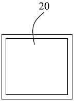
[0063] Step S03 , placing the first diode chip 20 with the cathode facing downwards and the anode facing upwards on the first solder paste 1 for soldering.

[0064] Step S04 , applying or brushing the second solder paste 2 on the anode of the first diode chip 20 .

[0065] Step S05 , placing the anode copper sheet 30 on the second solder paste 2 for welding, and welding the anode copper sheet 30 to one pin 12 of the conductive support 10 .

[0066] Step S06 , applying or br...


PUM


Abstract

The invention provides a common anode diode device and its preparation method. The device comprises: a conductive support including a heat sink and at least two pins arranged on one side of the heat sink; a first diode chip with its cathode facing downward Upward soldering on the heat sink; anode copper sheet, stacked and welded on the anode of the first diode chip; second diode chip, its cathode facing up and anode facing down, laminated and soldered on the anode copper sheet On the top: the cathode copper sheet is stacked and welded on the cathode of the second diode chip; wherein, the anode copper sheet and the cathode copper sheet are respectively welded to one of the pins. In the present invention, the anodes of the two diode chips are face-to-face welded to the anode copper sheet in the middle, and the anode copper sheet is welded to one of the pins of the copper bracket, so as to lead out the plastic package and realize the common anode, so that the two diode chips The cathode faces outward, while the anode is welded with a large area of ​​copper sheet, which can significantly improve the heat dissipation and surge capability of the device.

Description

technical field [0001] The invention relates to the technical field of electronic devices, in particular to a common anode diode device and a preparation method thereof. Background technique [0002] Diode is one of the most commonly used electronic components. Its biggest characteristic is unidirectional conduction, that is, current can only flow from one direction of the diode. The function of the diode is a rectifier circuit, a detection circuit, a voltage stabilization circuit, and various modulation circuits. , are mainly composed of diodes. [0003] In some circuits, it is necessary to use two diodes to realize the common anode connection relationship, and it is necessary to add a common anode diode device. Currently, common anode diode devices are typically packaged with two diodes and a copper standoff. [0004] Because the heat dissipation of the diode chip is mainly through the cathode, but in the current packaging method, the cathode of the diode cannot be direc...

Claims


Application Information

Patent Timeline
Patent Type & Authority Patents(China)
IPC IPC(8): H01L25/07H01L29/861H01L23/367H01L23/495H01L21/50
CPCH01L25/074H01L29/861H01L23/3672H01L23/3677H01L23/49568H01L23/49562H01L21/50H01L2224/40245
Inventor 陆爱华黄华兴陈松
Owner 瑞能微恩半导体(上海)有限公司
Why Eureka
Try Eureka