Heat pipe synergetic air conditioner refrigerating system
A technology of air-conditioning refrigeration and air-conditioning condenser, which is applied in the field of heat pipe cooperative air-conditioning and refrigeration systems, and can solve the problem of high energy consumption
- Summary
- Abstract
- Description
- Claims
- Application Information
AI Technical Summary
Problems solved by technology
Method used
Image
Examples
Embodiment 1
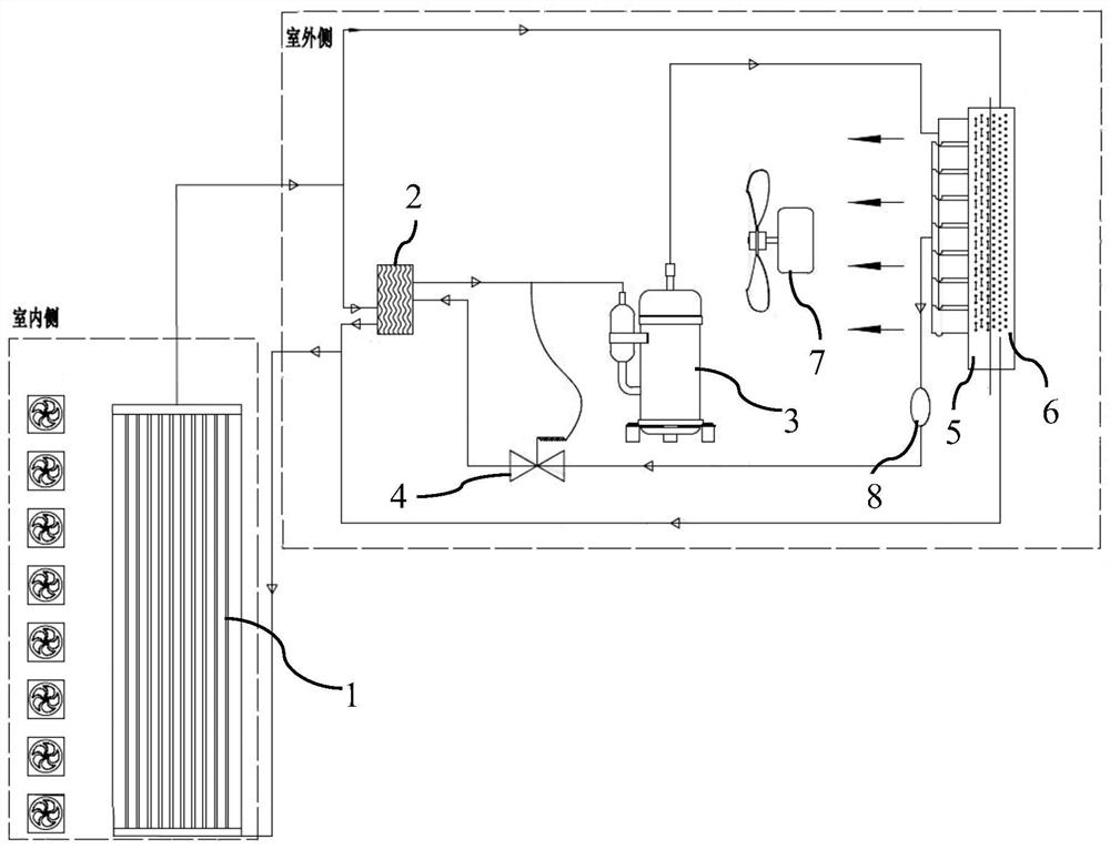
[0033] See attached figure 1 and 2 , a heat pipe cooperative air-conditioning and refrigeration system, including a micro-channel heat exchanger 1 arranged on the indoor side and an outdoor unit arranged on the outdoor side, the outdoor unit includes a plate heat exchanger 2, a compressor 3, a thermal expansion valve 4, and an air-conditioning condensing Device 5, heat pipe heat exchanger 6.
[0034] The micro-channel heat exchanger 1 inside the chamber is used as an evaporator, and the refrigerant in the micro-channel heat exchanger is evaporated into a gas phase by absorbing heat in the chamber.
[0035] The inlet of the microchannel heat exchanger 1 on the indoor side is located at the bottom of the microchannel heat exchanger, and the outlet is arranged on the top of the microchannel heat exchanger. The bottom outlet of the heat exchanger 6 is connected, and the top outlet of the microchannel heat exchanger 1 is connected with the top inlet of the heat pipe heat exchange...
Embodiment 2
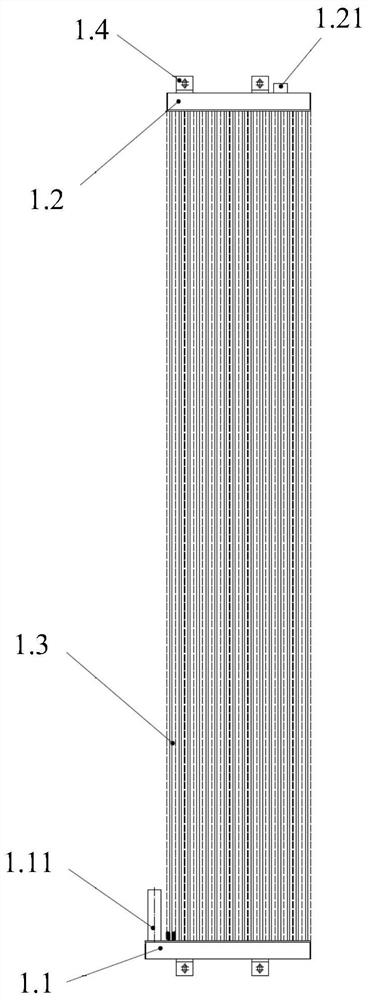
[0043] See attached image 3 , is a structural schematic diagram of the microchannel heat exchanger on the indoor side. The microchannel heat exchanger includes a liquid inlet header 1.1, an air outlet header 1.2 and a heat transfer tube 1.3 with cooling fins. The liquid header is located at the bottom, The gas outlet header is located on the upper part, and the liquid inlet header and the gas outlet header are arranged parallel to each other. The inlet connector 1.11 is arranged on the inlet header, and the inlet connector is vertically arranged upwards to the liquid inlet header. The outlet header is provided with an outlet connector 1.21. , the outlet connecting pipe is arranged vertically to the outlet header; the number of heat transfer tubes with cooling fins is multiple, arranged between the liquid inlet header and the outlet header, and the heat transfer tubes with cooling fins The two ports of the heat transfer tube are connected with the liquid inlet header and the g...
Embodiment 3
[0045] See attached Figure 4 , is the structural diagram of the heat pipe heat exchanger. The heat pipe heat exchanger includes an inlet header 6.1, a liquid outlet header 6.2 and a heat transfer tube 6.3 with cooling fins. The inlet header is vertically located on the left side, and the liquid outlet The header is vertically located on the right, and the inlet header is provided with an inlet connector 6.11, which is located at the upper part of the inlet header, and an outlet connector 6.21 is arranged on the outlet header, and the outlet connector is located at the lower part of the outlet header; The number of heat transfer tubes with cooling fins is multiple, arranged between the inlet header and the liquid outlet header, and the two ports of the heat transfer tubes with cooling fins are respectively connected to the inlet header and the outlet header. The liquid outlet headers are connected; the heat transfer tube with cooling fins is an integrated structure, and the co...
PUM
 Abstract
Description
Claims
Application Information
 - R&D Engineer
- R&D Manager
- IP Professional
- Industry Leading Data Capabilities
- Powerful AI technology
- Patent DNA Extraction
Browse by: Latest US Patents, China's latest patents, Technical Efficacy Thesaurus, Application Domain, Technology Topic, Popular Technical Reports.
© 2024 PatSnap. All rights reserved.Legal|Privacy policy|Modern Slavery Act Transparency Statement|Sitemap|About US| Contact US: help@patsnap.com


