
Semiconductor stack for hall effect device

A Hall effect, semiconductor technology, applied in the field of semiconductor stacking of Hall effect devices

Active Publication Date: 2021-08-17
メレクシステクノロジーズソシエテアノニム
View PDF3 Cites 0 Cited by
  • Summary
  • Abstract
  • Description
  • Claims
  • Application Information

AI Technical Summary

Problems solved by technology

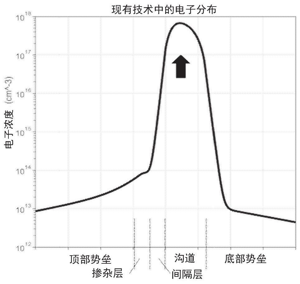
[0007] However, reducing the Al composition in AlGaAs in the barrier region preventing the DX center lowers the conduction band bottom, which reduces the conduction band shift between the spacer and the channel, resulting in a larger thermally activated realization. space electron transfer

Method used


Image

  • Semiconductor stack for hall effect device
  • Semiconductor stack for hall effect device
  • Semiconductor stack for hall effect device

Examples


Embodiment Construction

[0044] The present invention will be described with respect to particular embodiments and with reference to certain drawings but the invention is not limited thereto but only by the claims. The drawings described are only schematic and non-limiting. In the drawings, the size of some of the elements may be exaggerated and not drawn on scale for illustrative purposes. The dimensions and relative dimensions do not correspond to actual reductions to the practice of the invention.

[0045]The terms first, second, etc. in the description and claims are used to distinguish between similar elements and not necessarily to describe an order in time, space, hierarchy or in any other way. It is to be understood that the terms so used are interchangeable under appropriate circumstances and that the embodiments of the invention described herein are capable of operation in other sequences than described or illustrated herein.

[0046] Furthermore, the terms top, below, etc. in the descript...


PUM

PropertyMeasurementUnit
thicknessaaaaaaaaaa
thicknessaaaaaaaaaa
thicknessaaaaaaaaaa

Abstract

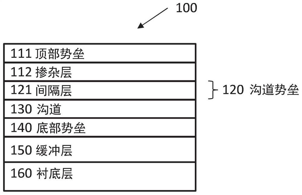
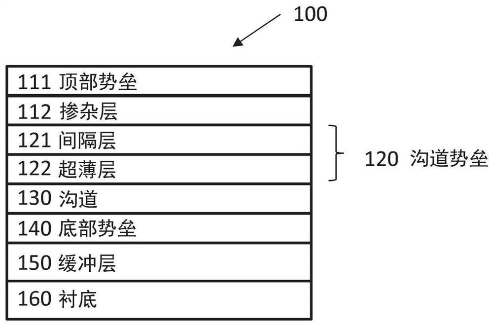
The invention discloses a semiconductor stack for hall effect device. The semiconductor stack (100) for a Hall effect device comprises: a bottom barrier (140) comprising AlxGa1-xAs, a channel (130) comprising InyGa1-yAs, on the bottom barrier (140), a channel barrier (120) with a thickness which is at least 2 nm and which is smaller than or equal to 15 nm, and which at least comprises a first layer (121) comprising AlzGa1-zAs with 0.1 <= z <= 0.22, wherein the first layer (121) has a thickness of at least 2 nm, wherein a conduction band edge of the bottom barrier (140) and the first layer (121) is higher than a conduction band edge of the channel (130), a doping layer (112) comprising a composition of Al, Ga and As and doped with n-type material, and a top barrier (111) comprising a composition of Al, Ga and As.

Description

technical field [0001] The present invention relates to the field of semiconductor stacks. More specifically, the present invention relates to semiconductor stacks for Hall effect devices. Background technique [0002] A typical III-V epitaxial (epi) stack used as a Hall sensing element in the prior art includes a barrier region and a channel between the bottom barrier. The barrier region and the bottom barrier are materials with a higher conduction band edge, and the channel is a material with a lower conduction band edge, thereby forming a quantum well. Electrons are confined in the channel layer, forming a two-dimensional electron gas with high electron mobility. Doped layers are often referred to as delta doped. [0003] Achieving both high sheet resistance and low low frequency (LF) noise in III-V epitaxial stacks has long been a goal of substrates for Hall effect applications. On the one hand, high sheet resistance provides higher voltage-dependent magnetic sensiti...

Claims


Application Information

Patent Timeline
Patent Type & Authority Applications(China)
IPC IPC(8): H01L43/06H01L43/04H01L43/14H10N52/00H10N52/01H10N52/80
CPCH10N52/80H10N52/01H10N52/101H01L29/205H01L29/122
Inventor 何冠霆L·巴尔比
Owner メレクシステクノロジーズソシエテアノニム
Learn More