Engine in-cylinder braking mechanism and method

A technology of engine cylinder and braking mechanism, applied in the direction of engine components, machines/engines, mechanical equipment, etc., can solve the problems of low braking efficiency, inability to realize secondary compression and release braking of exhaust stroke, etc.

Active Publication Date: 2021-08-20
LONGKOU ZHONGYU THERMAL MANAGEMENT SYST SCIAND TECH
View PDF6 Cites 5 Cited by
  • Summary
  • Abstract
  • Description
  • Claims
  • Application Information

AI Technical Summary

Problems solved by technology

[0007] 3. The gas will prevent the piston from going down (the piston is equivalent to vacuuming), and generate a torque effect on the crankshaft in the opposite direction, thereby producing a braking effect
The characteristic of this in-cylinder braking mechanism is that th

Method used


Image

  • Engine in-cylinder braking mechanism and method
  • Engine in-cylinder braking mechanism and method
  • Engine in-cylinder braking mechanism and method

Examples


Embodiment 1

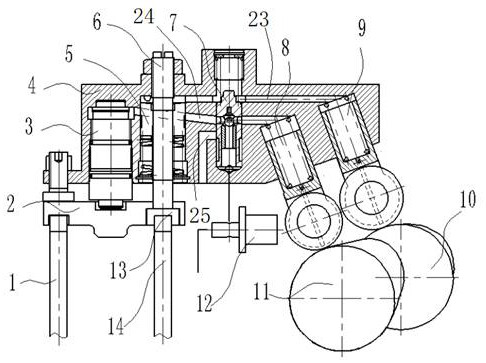
[0042] In a typical embodiment of the present invention, such as figure 2 As shown, an engine in-cylinder braking mechanism is proposed, including: a main part, a pressure building mechanism, an actuator, a control part, etc.

[0043] Wherein, the housing 4 constitutes the main part of the braking mechanism in the engine cylinder; the brake cam 10, the exhaust cam 11, the exhaust tappet 8, and the braking tappet 9 constitute the pressure building mechanism of the braking mechanism in the engine cylinder; Piston 3, brake piston 5, and valve bridge 2 form the actuator of the braking mechanism in the engine cylinder; the switching valve and the control solenoid valve 12 form the control part of the braking mechanism in the engine cylinder.

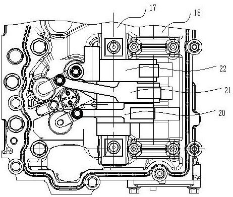
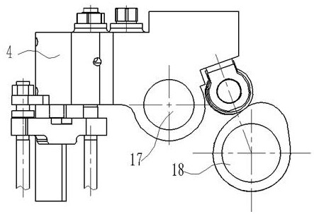
[0044] The fixing method of the housing 4 can adopt the method of being sleeved on the rocker arm shaft 17 of the traditional diesel engine and adding the auxiliary support of the housing leg 27, or can be directly fixed on the rocker arm sh...

Embodiment 2

[0064] This embodiment proposes the working method of the above-mentioned engine in-cylinder braking mechanism, comprising the following steps:

[0065] When the switching valve disconnects the brake oil circuit 23, the exhaust oil circuit 24 is conducted, and the exhaust tappet 8 generates high-pressure oil to drive the hydraulic piston 3, and then pushes the exhaust valve Ⅰ 1 and exhaust valve Ⅱ through the valve bridge 2 14 movement to achieve exhaust;

[0066] When the switching valve disconnects the exhaust oil circuit 24, the brake oil circuit 23 is connected, and the brake tappet 9 generates high-pressure oil to drive the brake piston 5, and then pushes the exhaust valve II 14 to move to realize braking.

[0067] During the braking process, after the first compression braking, the exhaust valve II 14 is further opened to perform secondary air intake during the power stroke, and then compressed and released during the exhaust stroke to achieve two in-cylinder braking;

...


PUM


Abstract

The invention discloses an engine in-cylinder braking mechanism and a method, belongs to the technical field of engine braking, and aims at solving the problems that an existing in-cylinder braking mechanism cannot achieve secondary compression release braking in the exhaust stroke and is low in braking efficiency. According to the technical scheme of the engine in-cylinder braking mechanism, the engine in-cylinder braking mechanism comprises a shell body, a hydraulic piston and a braking piston are arranged in the shell body, the hydraulic piston is connected with an exhaust valve I and an exhaust valve II through a valve bridge, the exhaust valve II is connected with the braking piston, the hydraulic piston is connected with an exhaust tappet through an exhaust oil way, the braking piston is connected with a braking tappet through a braking oil way, and the exhaust oil way and the braking oil way are both connected with a change-over valve. The change-over valve can control one of the exhaust oil way and the braking oil way to be disconnected so as to switch between the exhaust state and the braking state, and two times of compression release brake of an engine in one working cycle are achieved.

Description

technical field [0001] The invention belongs to the technical field of engine braking, and in particular relates to an engine in-cylinder braking mechanism and method. Background technique [0002] The statements herein merely provide background information related to the present invention and do not necessarily constitute prior art. [0003] In-cylinder braking is to use the compression resistance generated by the compression stroke of the engine, the internal friction force and the intake and exhaust resistance to form a braking effect on the driving wheel. [0004] The main principle of in-cylinder braking is: [0005] 1. In-cylinder braking means that when the accelerator is released, the exhaust valve opens instantly when the piston is near the upper pole during the compression stroke to release the high-pressure gas; [0006] 2. Close the exhaust valve, there is very little gas in the cylinder, and the cylinder is in a negative pressure state when the piston moves fr...

Claims


Application Information

Patent Timeline
IPC IPC(8): F01L13/06F01L9/14F01L9/40
CPCF01L13/065
Inventor 王兆宇李小霞郑建松李光明于林善迟广军
Owner LONGKOU ZHONGYU THERMAL MANAGEMENT SYST SCIAND TECH
Why Eureka
Try Eureka