
MIMO radar target positioning method and system based on space-time coding

A space-time coding and radar target technology, applied in radio wave measurement system, radio wave reflection/re-radiation, instruments, etc., can solve the problems of large hardware resource consumption, poor angular resolution, low positioning accuracy, etc., and achieve complex The effects of clean wave background, improved angular resolution, and improved positioning accuracy

Pending Publication Date: 2021-08-20
HUAZHONG UNIV OF SCI & TECH
View PDF5 Cites 2 Cited by
  • Summary
  • Abstract
  • Description
  • Claims
  • Application Information

AI Technical Summary

Problems solved by technology

Generally speaking, MIMO radar requires that the transmitted waveforms are mutually orthogonal and have good autocorrelation and cross-correlation characteristics, but it is not easy to design multiple waveforms that meet this condition
Existing MIMO radar positioning technology generally designs better orthogonal waveforms to meet positioning requirements through special methods, but such methods are complex and require a lot of hardware resources; in terms of signal processing, traditional MIMO radar-based The positioning method is usually carried out in two steps, that is, the distance of the target is estimated by Fast Fourier Transform (FFT), and then the angle of the target is estimated by digital beamforming or one-dimensional spectrum estimation algorithm, so as to realize the positioning of the target
However, this method has the disadvantages of poor angular resolution and low positioning accuracy.

Method used


Image

  • MIMO radar target positioning method and system based on space-time coding
  • MIMO radar target positioning method and system based on space-time coding
  • MIMO radar target positioning method and system based on space-time coding

Examples


Embodiment Construction

[0029]In order to make the object, technical solution and advantages of the present invention clearer, the present invention will be further described in detail below in conjunction with the accompanying drawings and embodiments. It should be understood that the specific embodiments described here are only used to explain the present invention, not to limit the present invention. In addition, the technical features involved in the various embodiments of the present invention described below can be combined with each other as long as they do not constitute a conflict with each other.

[0030] In the present invention, the terms "first", "second" and the like (if any) in the present invention and drawings are used to distinguish similar objects, and are not necessarily used to describe a specific order or sequence.

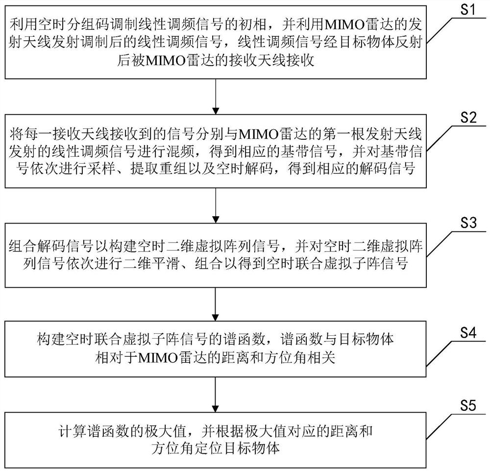
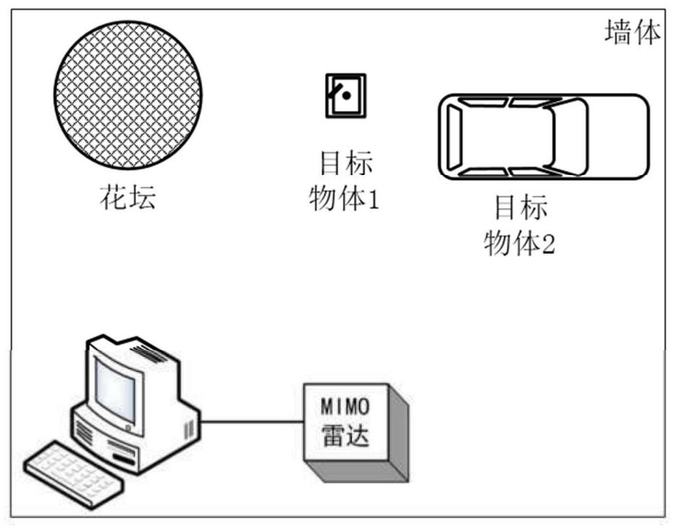
[0031] figure 1 It is a flowchart of a space-time coding-based MIMO radar target location method provided by an embodiment of the present invention. refer to fig...


PUM


Abstract

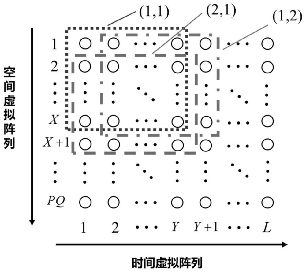
The invention discloses an MIMO radar target positioning method and system based on space-time coding, and belongs to the field of target detection and positioning, wherein the method comprises the steps: modulating the initial phase of linear frequency modulation signals through a space-time block code, transmitting the linear frequency modulation signals, and receiving the signals through receiving antennas after the signals are reflected by a target object; performing frequency mixing on the signals received by all the receiving antennas and the signal transmitted by the first transmitting antenna to obtain baseband signals, and performing sampling, extraction recombination and space-time decoding on the baseband signals in sequence to obtain corresponding decoded signals; combining the decoded signals to construct space-time two-dimensional virtual array signals, and sequentially performing two-dimensional smoothing and combination on the space-time two-dimensional virtual array signals to obtain space-time combined virtual sub-array signals; constructing a spectral function of the space-time joint virtual sub-array signals; and calculating the maximum value of the spectral function, and positioning the target object according to the distance and azimuth angle corresponding to the maximum value. The angle estimation precision can be improved, a clutter background is cleaner, target detection is facilitated, and the positioning precision is improved.

Description

technical field [0001] The invention belongs to the field of target detection and positioning, and more particularly relates to a space-time coding-based MIMO radar target positioning method and system. Background technique [0002] Multi-target positioning technology has a wide range of applications, such as smart transportation, indoor positioning, etc. Compared with infrared, laser, ultrasonic and other detection technologies, radar is almost not affected by the weather, has the characteristics of all-weather and all-weather, and has certain penetration capabilities. In scenes with low visibility such as fire scenes and foggy weather, the radar also has stable multi-target positioning performance. [0003] Multiple-input-multiple-out (MIMO) radar is a multi-antenna combined transceiver system. Technologies such as waveform diversity, space diversity and time diversity enable it to have high resolution, flexible beam design, anti-target scintillation and anti-jamming, etc...

Claims


Application Information

Patent Timeline
IPC IPC(8): G01S13/06
CPCG01S13/06Y02A90/10
Inventor 谢锐高扬邓彧俊罗锴
Owner HUAZHONG UNIV OF SCI & TECH
Learn More