
Shot-slag separation device

A slag separation and separation plate technology, which is applied in solid separation, used abrasive treatment device, and air flow to separate solids from solids, etc. And other issues

Pending Publication Date: 2021-08-24
SHANDONG KAITAI SHOT BLASTING MACHINERY
View PDF11 Cites 0 Cited by
  • Summary
  • Abstract
  • Description
  • Claims
  • Application Information

AI Technical Summary

Problems solved by technology

This separation method can only separate the dust with small particle size, but not other slag materials.
[0006] Chinese patent document CN209812066U discloses a multistage separator for a shot blasting machine, which has four stages of separation steps, the first stage being filtration, as previously mentioned, the filtration is affected by the wide particle size distribution of the slag material, and often the separation is very poor. It is sufficient, but the large slag can be directly filtered out, and the remaining fine slag is sent to the next stage along with the projectile, and then enters the wind separation after two stages of separation, but it still adopts the method of suction separation, which cannot be separated by suction. Form a beam, the separation efficiency is relatively low, and only fine materials with a relatively large specific surface area can be separated

Method used


Image

  • Shot-slag separation device
  • Shot-slag separation device

Examples


Embodiment Construction

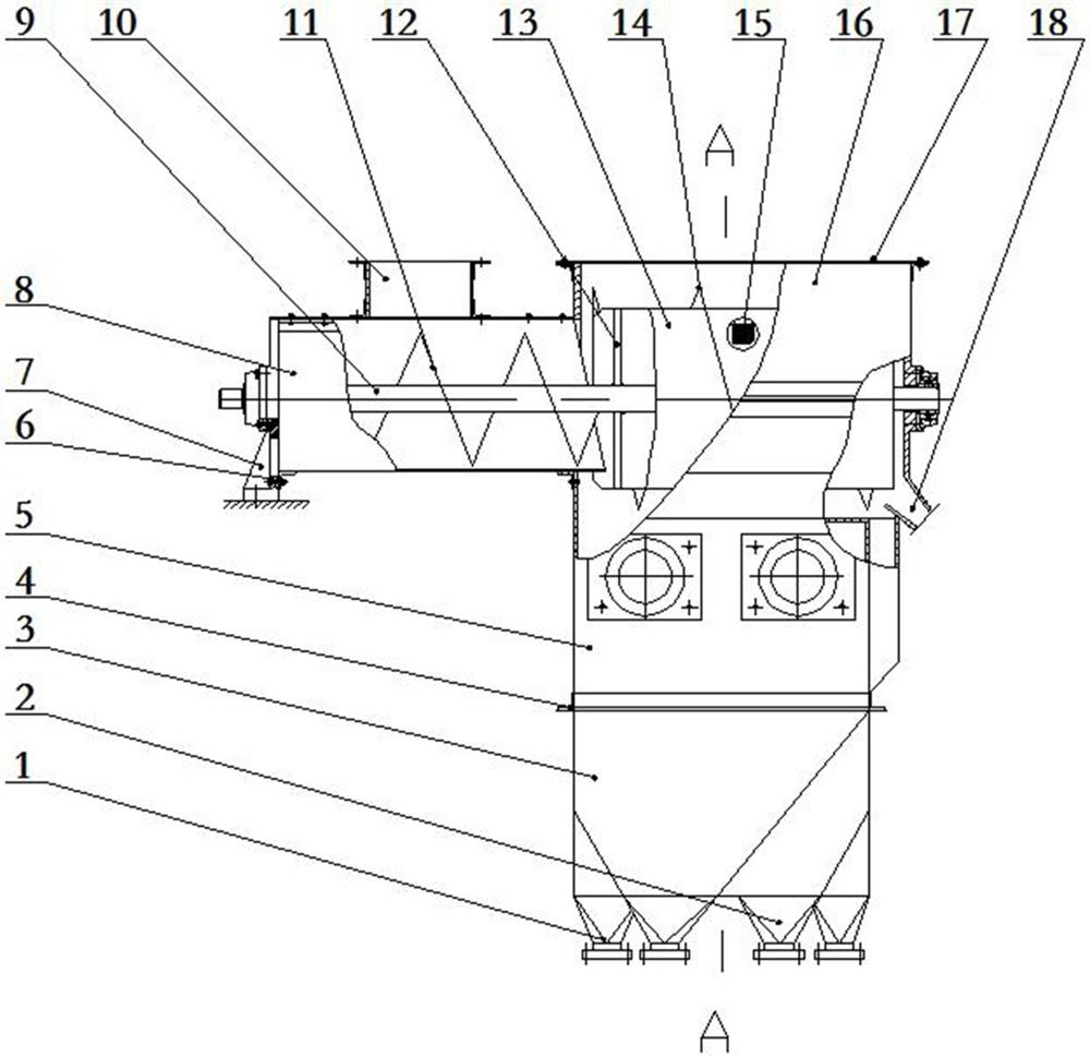
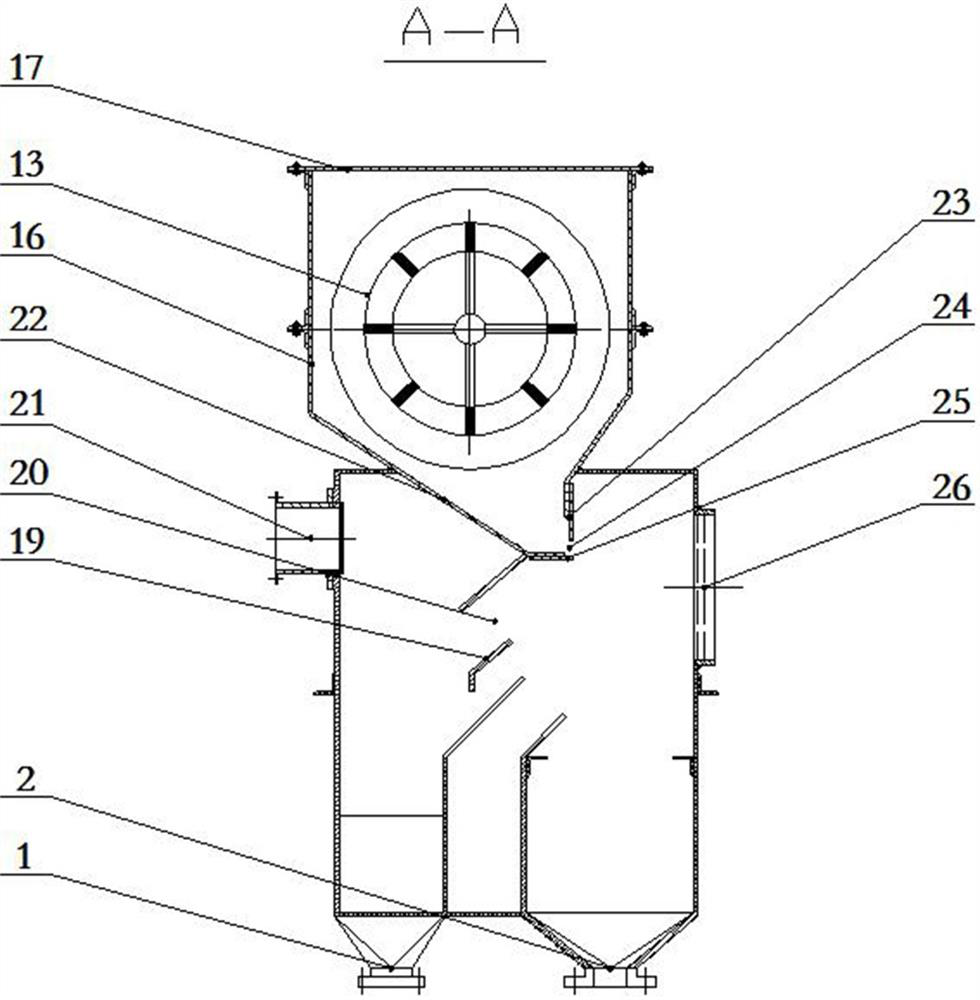
[0038] Attached from the manual figure 1 and figure 2 It can be seen from the pellet and slag separation device shown in that the separation link includes two parts, one is screening, and the other is winnowing. Compared with multiple links in the prior art, there are only two links, of which the first One link, that is, screening, is screening in motion. Specifically, the screw conveyor screens during the conveying process. As the material moves forward, part of the material is screened, and the remaining material is less and less. Avoid static For the problem of mutual superimposition of the lower screening materials, the screening effect is relatively good, and the feeding is continuous, which does not affect the screening efficiency. The part that cannot be screened is directly discharged from the end of the screening part. In the conventional scheme, the wind selection mainly adopts the air extraction method, because there are many air leakage points in the pellet and ...


PUM


Abstract

The invention discloses a shot-slag separation device. The shot-slag separation device comprises a spiral conveyor, a screen drum, a slag feeding opening, a material guiding assembly, a separation bin, a separation plate, a shot opening and a slag opening. According to the shot-slag separation device, a shot curtain is constructed, separation is achieved through winnowing, in addition, screening is conducted through the screen drum at the preceding stage, and the number of separation links is small but the separation effect is relatively good based on the shot-slag separation device.

Description

technical field [0001] The invention relates to a shot slag separating device, which is used for separating projectiles from the shot slag material recovered in the shot blasting process. Background technique [0002] As an important means of cleaning the surface of workpieces such as castings, the shot blasting process has attracted widespread attention and application. The wide use of the shot blasting process is bound to have a relatively strong demand for projectiles. Although projectiles are consumables, projectiles can be reused. , so the recycling of projectiles has become an important auxiliary process for shot blasting. [0003] Due to the large amount of projectiles used, it is not suitable for manual separation of shot and slag; because the particle size distribution of slag is relatively wide, and the particle size of projectiles used in the same shot blasting process is relatively uniform, so the method of screening cannot be used for shot blasting. Effective s...

Claims


Application Information

Patent Timeline
IPC IPC(8): B07B1/24
CPCB07B1/24B07B1/42B07B1/46B07B7/01B07B11/06B24C9/006
Inventor 王守仁张肖王健袁存波郭培全苗清坤李翠玲
Owner SHANDONG KAITAI SHOT BLASTING MACHINERY
Learn More