High borosilicate glass product girdling device

A technology of high borosilicate glass and products, applied in glass cutting devices, glass manufacturing equipment, grinding drive devices, etc., can solve the problems of easy cutting damage, inaccurate cutting, difficult multi-station cutting, etc., and achieve cutting quality. Good, improve work efficiency, improve the effect of quality

Inactive Publication Date: 2021-08-24
江苏立晶工业科技有限公司
View PDF11 Cites 3 Cited by
  • Summary
  • Abstract
  • Description
  • Claims
  • Application Information

AI Technical Summary

Problems solved by technology

[0003] Due to the superiority of high borosilicate glass, the practical field is more and more extensive. However, in the process of making high borosilicate glass into products, some products are in the shape of a ring, which needs to be cut in a ring, and the cutting is not accurate enough. And it is easy to be damaged when cutting, the safety is not high, and the cutting efficiency is low, it is difficult to perform multi-station cutting at the same time, which is time-consuming and laborious

Method used


Image

  • High borosilicate glass product girdling device
  • High borosilicate glass product girdling device
  • High borosilicate glass product girdling device

Examples


Embodiment 1

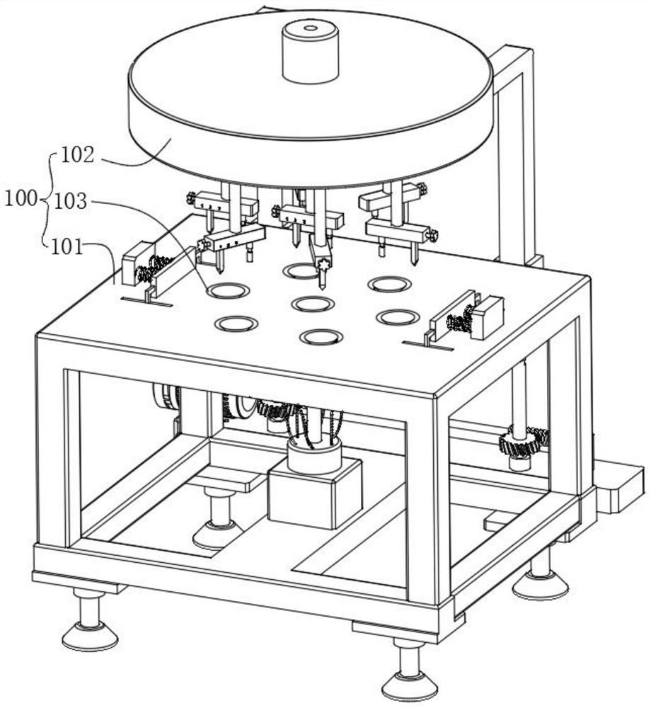
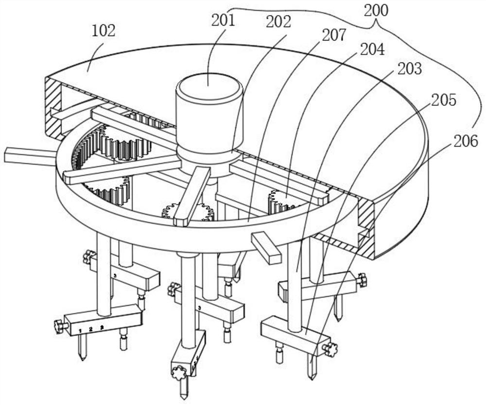
[0051] combine figure 1 , 2 As shown in and 3, the high borosilicate glass product ring cutting device provided by the present invention includes a body 100, a cutting mechanism 200, an adjustment mechanism 300, a lifting mechanism 400 and a positioning mechanism 500. The body 100 includes a workbench 101 and a workbench 101 The casing 102 above and a plurality of transmission holes 103 opened on the workbench 101, the cutting mechanism 200 includes a first motor 201 fixed on the casing 102, a transmission frame 202 fixed on the output end of the first motor 201, a fixed The gear ring 207 connected to the bottom of the transmission frame 202, the plurality of transmission shafts 203 rotatably mounted on the bottom of the housing 102, the gear 204 fixed on the top of the transmission shaft 203 and meshed with the gear ring 207, and fixed on the bottom of the transmission shaft 203 The connection box 205 at the end and the cutting knife 206 arranged at the bottom of the connect...

Embodiment 2

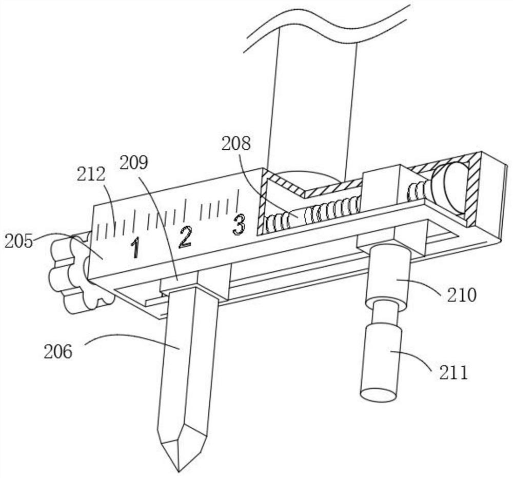
[0057] combine figure 2 with 5 As shown, on the basis of Embodiment 1, the adjustment mechanism 300 includes a second motor 301 installed on the workbench 101, an output shaft fixed to the output end of the second motor 301, a worm screw 302 sleeved on both sides of the output shaft, and Rotate and install the screw rod 303 on both sides of the workbench 101, the worm wheel 305 that is sleeved on the screw rod 303 and meshes with the worm screw 302 for transmission, and the connecting sleeve 304 that is suitable for sliding relative to the screw rod 303. The end of the connecting sleeve 304 is fixedly connected with the housing 102. The second motor 301 starts to drive the output shaft to rotate, the worm 302 rotates with the output shaft, the worm 302 and the worm wheel 305 are meshed for transmission, and the worm 302 drives the screw 303 to rotate through the worm wheel 305, so that the connecting sleeve 304 moves, and the housing 102 follows the connection The sleeve 304...

Embodiment 3

[0059] combine image 3 with 6 As shown, in the above embodiment, the lifting mechanism 400 includes a vacuum glass hoist 401, a suction cup arranged on the vacuum glass hoist 401, an electric push rod 402 placed on the vacuum glass hoist 401, and affixed to The connecting frame 403 at the end of the electric push rod 402 and a plurality of ejector rods 404 fixed on the connecting frame 403, the top of the ejector rod 404 is fixedly connected with the suction cup, the suction cup is located in the transmission hole 103, and the vacuum glass suction hoist 401 passes through the suction cup Suction is generated to fix the material and avoid shaking during cutting, so that the cutting quality of the material is better, and the electric push rod 402 pushes the connecting frame 403 to rise, and the ejector rod 404 rises with the vacuum glass suction hoist 401, and then the cutting can be carried out. The finished product is lifted up, which is convenient for the staff to process t...


PUM


Abstract

The invention discloses a high borosilicate glass product girdling device which comprises a machine body, a cutting mechanism, an adjusting mechanism, a lifting mechanism and positioning mechanisms. The machine body comprises a workbench, a shell arranged above the workbench and a plurality of transmission holes formed in the workbench. The cutting mechanism comprises a first motor fixedly installed on the shell, a transmission frame fixedly connected to the output end of the first motor, a gear ring fixedly connected to the bottom of the transmission frame, a plurality of transmission shafts rotationally installed at the bottom of the shell, gears fixedly connected to the top ends of the transmission shafts and in meshing transmission with the gear ring, a connecting box fixedly connected to the bottom end of the transmission shafts, and a cutting knife arranged at the bottom of the connecting box; and the bottom end of the transmission shaft extends to the position below the shell and used for adjusting the height of the cutting mechanism, the lifting mechanism is located in the shell and used for lifting and fixing materials, and the positioning mechanisms are arranged on the two sides of the workbench and used for positioning the materials. Dangerous caused by manual cutting can be avoided, and multi-station machining is achieved through the single first motor.

Description

technical field [0001] The invention relates to the technical field of high borosilicate glass, in particular to a ring cutting device for high borosilicate glass products. Background technique [0002] High borosilicate glass (also known as hard glass) is a special glass with high temperature resistance and low expansion coefficient. It is a low expansion rate, high temperature resistance, high strength, high hardness, high light transmittance and high chemical stability. Due to its excellent performance, it is widely used in solar energy, chemical industry, pharmaceutical packaging, electric light source, craft jewelry and other industries. The good performance of high borosilicate glass has been widely recognized by all walks of life in the world, especially in the field of solar energy The application is more extensive, and developed countries such as Germany and the United States have carried out extensive promotion. [0003] Due to the superiority of high borosilicate...

Claims


Application Information

Patent Timeline
Patent Type & Authority Applications(China)
IPC IPC(8): C03B33/04B24B9/10B24B27/00B24B47/12
CPCB24B9/10B24B27/0023B24B27/0076B24B47/12C03B33/04
Inventor 邵长顺
Owner 江苏立晶工业科技有限公司
Why Eureka
Try Eureka