Kitchen waste compost fermentation tank capable of preventing odor from drifting away
The technology of kitchen waste and fermentation tank is applied in the directions of organic fertilizers, fertilization devices, preparation of organic fertilizers, etc., which can solve the problems of inconvenient addition of fungus powder, odor easily scattered, inconvenient to take, etc. The effect of avoiding air pollution and speeding up the fermentation process
- Summary
- Abstract
- Description
- Claims
- Application Information
AI Technical Summary
Problems solved by technology
Method used
Image
Examples
Embodiment 1
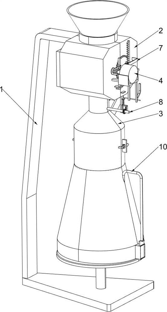
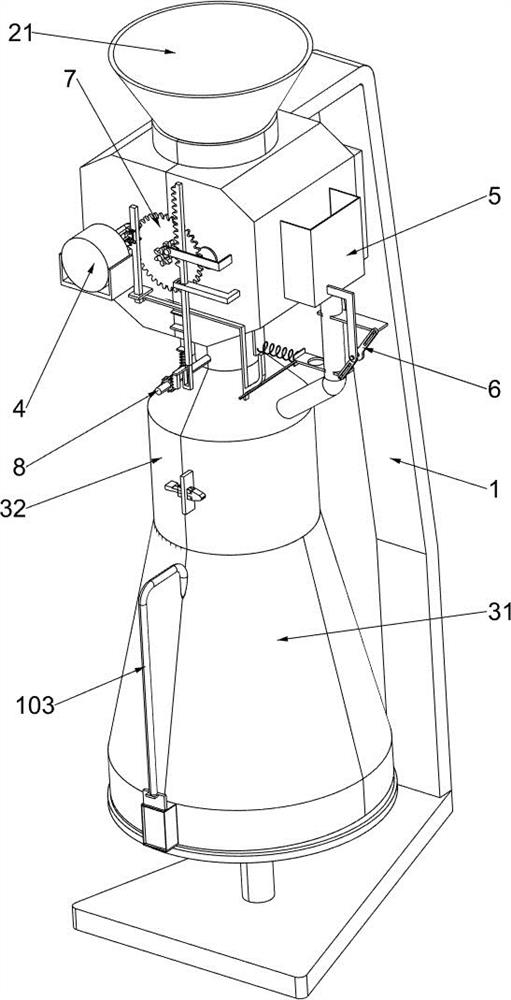
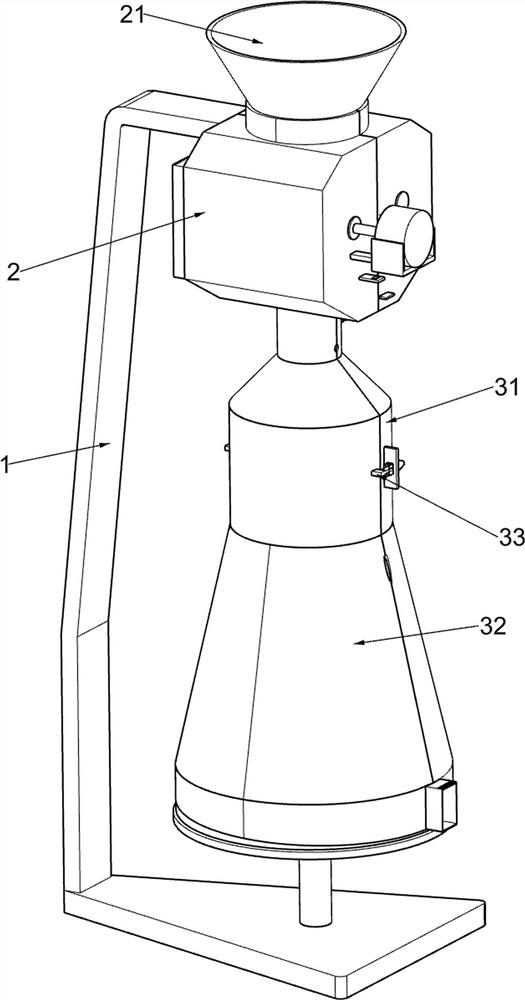
[0032] A kitchen waste composting fermenter capable of preventing odor from dispersing, such as Figure 1-9As shown, it includes a support plate 1, a crushing frame 2, a funnel 21, a combined clamping assembly 3 and a crushing assembly 4, a crushing frame 2 is fixedly installed on the right side of the support plate 1, a funnel 21 is fixedly connected above the crushing frame 2, and the crushing frame 2 is provided with a combined clamping assembly 3 for preventing odor from dispersing, and a crushing assembly 4 is provided on the crushing frame 2 for crushing large particles of kitchen waste in the upper part of the crushing frame 2 to be treated.
[0033] The combined clamping assembly 3 includes a fixed fermentation tank body 31, a fermentation clamping frame 32, a clamping plate 33, a movable clamping plate 34 and a torsion spring 35, and a fixed fermentation tank body 31 is fixedly connected to the bottom of the crushing frame 2, and a fixed fermentation tank body 31 It i...
Embodiment 2
[0037] On the basis of Example 1, such as Figure 6-7 As shown, it also includes a bacteria powder adding assembly 5, which is used to quantitatively add the bacteria powder to the inside of the fixed fermentation tank body 31. The bacteria powder adding assembly 5 is arranged on the crushing frame 2, and the bacteria powder adding assembly 5 includes Power gear 51, lifting rack 52, telescopic tooth plate 53, compression spring 54, inclined frame 541, bacteria powder frame 55, discharge pipe 56, discharge plate 57, fixed round rod 58 and tension spring 1 59, power shaft 43 The upper is fixedly connected with a power gear 51 for driving the lifting rack 52 and its upper device to move downward, and the right side of the crushing frame 2 is slidingly connected with a lifting rack 52. The telescopic tooth plate 53 is slidingly connected, and the compression spring 54 is symmetrically connected between the telescopic tooth plate 53 and the lifting rack 52. Through the cooperation ...
Embodiment 3
[0041] On the basis of Example 2, such as Figure 8 As shown, the stroke reduction assembly 7 is also included, and the stroke reduction assembly 7 is arranged on the crushing frame 2. The stroke reduction assembly 7 includes a rotating rod 71, a large rotating gear 72, an L-shaped frame 73, a transmission rod 74 and a transmission pinion 75 The right side of the crushing frame 2 is rotationally connected with a rotating rod 71, and the rotating rod 71 is fixedly connected with a large rotating gear 72, and the rotating large gear 72 meshes with the power gear 51, and the right side of the crushing frame 2 is fixedly connected with an L-shaped frame 73, L Rotation is connected with transmission rod 74 on the shape frame 73, is fixedly connected with transmission pinion 75 on the transmission rod 74, and the transmission pinion 75 on the transmission rod 74 can drive and push tooth bar 81 to move downwards, and is fixedly connected on the rotation rod 71 equally. There is trans...
PUM
 Abstract
Description
Claims
Application Information
 - R&D
- Intellectual Property
- Life Sciences
- Materials
- Tech Scout
- Unparalleled Data Quality
- Higher Quality Content
- 60% Fewer Hallucinations
Browse by: Latest US Patents, China's latest patents, Technical Efficacy Thesaurus, Application Domain, Technology Topic, Popular Technical Reports.
© 2025 PatSnap. All rights reserved.Legal|Privacy policy|Modern Slavery Act Transparency Statement|Sitemap|About US| Contact US: help@patsnap.com


