Compressor with built-in oil separator

A compressor and oil separation technology, applied in the field of compressors, can solve problems such as low energy efficiency of compressor reliability systems, limited oil storage space, and discharge of lubricating oil, so as to improve safety and reliability, improve oil storage capacity, and relax The effect of manufacturing requirements

Pending Publication Date: 2021-08-24
SHANGHAI HIGHLY NEW ENERGY TECH CO LTD
View PDF0 Cites 0 Cited by
  • Summary
  • Abstract
  • Description
  • Claims
  • Application Information

AI Technical Summary

Problems solved by technology

[0002] With the further increase in the output of new energy vehicles, users have higher requirements for the performance of new energy vehicles. At present, the air conditioning and refrigeration systems of more new energy vehicles use scroll compressors. However, in order to ensure The body weight and internal installation space of new energy vehicles are designed reasonably, which often place higher requirements on the design of vehicle scroll compressors, which will inevitably make the structure of the compressor more compact and smaller, but this also causes the compressor itself The oil storage space for storing lubricating oil is relatively limited
At the same time, in order to better meet the market demand, the maximum speed of the scroll compressor is constantly increasing, and the high-speed operation of the compressor can easily cause a large amount of lubricating oil to be discharged into the system along with the refrigerant, thus causing the reliability of the compressor. performance issues and system inefficiencies

Method used


Image

  • Compressor with built-in oil separator
  • Compressor with built-in oil separator
  • Compressor with built-in oil separator

Examples


Embodiment approach

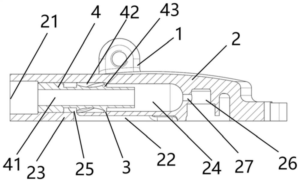
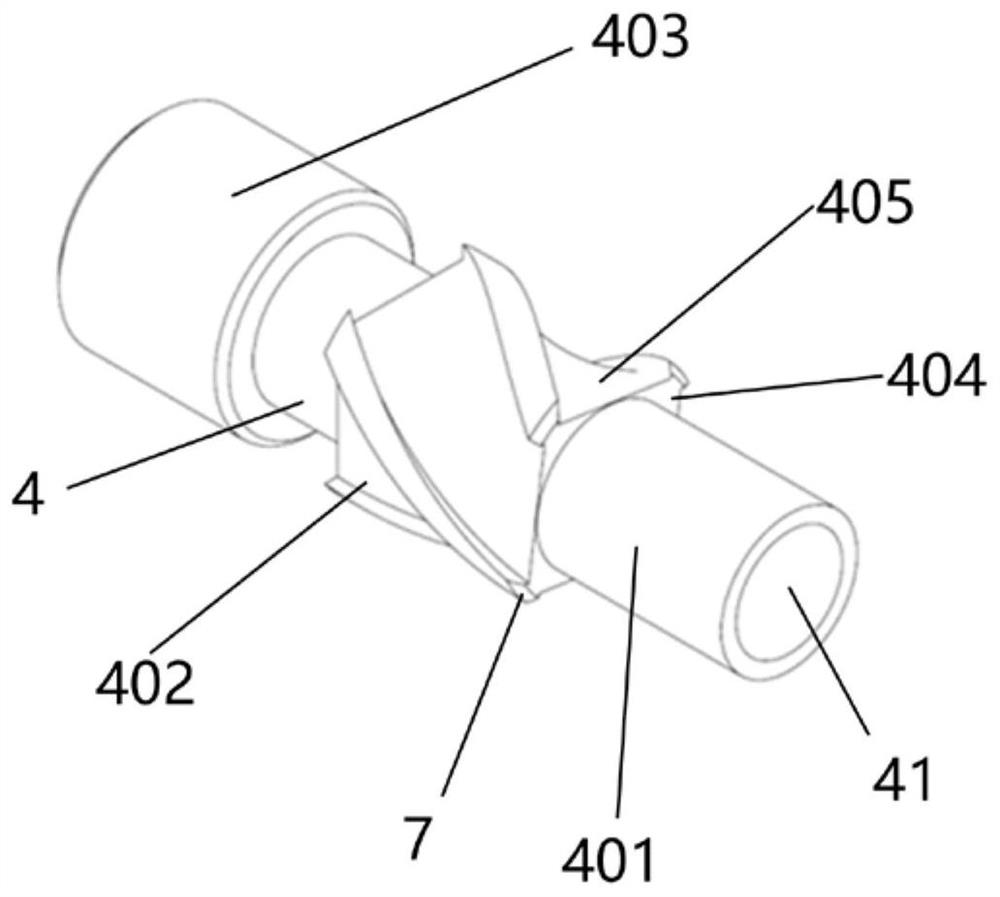
[0034] In a further embodiment of the present invention, the contact portion 43 is formed on the end of the spiral blade 402 away from the exhaust port 21, the contact portion 43 has at least one vertical contact surface 404 and at least one spiral connection surface 405, the vertical contact surface 404 One end is connected to the spiral connection surface 405, and a chamfer structure 7 is formed at the joint between the vertical contact surface 404 and the spiral connection surface 405, and the chamfer structure 7 has an abutment surface, and the abutment surface 7 and the stopper 3, the abutting surface and the axis of the oil channel 24 are set at an angle of 20°. Further, it facilitates the installation and axial positioning of the oil separation mandrel 4, and reduces the noise generated during operation.

[0035] Further, as a preferred embodiment, the stopper portion 3 is an annular surface, and the outer edge of the annular surface protrudes toward the exhaust port 21...


PUM


Abstract

The invention discloses a compressor with a built-in oil separator. The compressor comprises a compressor body; a shell provided with a front shell part, wherein the front shell part is provided with an exhaust port, and an exhaust cavity is formed between the front shell part and a static vortex; an oil separator shell arranged on the front shell part, wherein an oil separator channel is formed between the oil separator shell and the front shell part, the oil separator channel communicates with the exhaust port, the oil separator channel is provided with a stop part, an oil separator inlet is formed in the oil separator shell, and the oil separator inlet communicates with the oil separator channel and the exhaust cavity; and an oil separator core rod which is arranged in the oil separator channel, wherein an exhaust channel is arranged in the oil separator core rod, the exhaust channel communicates with the oil separator channel and the exhaust port, a spiral channel is formed between the oil separator core rod and the oil separator channel, the spiral channel communicates with the oil separator channel, the spiral channel communicates with the oil separator inlet, and a contact part is arranged on the oil separator core rod. Through the application of the compressor, the oil storage capacity of the compressor is improved, impurities are prevented from being generated in the installation process, and the safety and reliability of the compressor are further improved.

Description

technical field [0001] The invention relates to the technical field of compressors, in particular to a compressor with built-in oil. Background technique [0002] With the further increase in the output of new energy vehicles, users have higher requirements for the performance of new energy vehicles. At present, the air conditioning and refrigeration systems of more new energy vehicles use scroll compressors. However, in order to ensure The body weight and internal installation space of new energy vehicles are designed reasonably, which often place higher requirements on the design of vehicle scroll compressors, which will inevitably make the structure of the compressor more compact and smaller, but this also causes the compressor itself The oil storage space for storing lubricating oil is relatively limited. At the same time, in order to better meet the market demand, the maximum speed of the scroll compressor is constantly increasing, and the high-speed operation of the c...

Claims


Application Information

Patent Timeline
Patent Type & Authority Applications(China)
IPC IPC(8): F04C29/02
CPCF04C29/026
Inventor 黄志刚牟英涛李奇
Owner SHANGHAI HIGHLY NEW ENERGY TECH CO LTD
Why Eureka
Try Eureka