A power supply system applied to underwater equipment

A technology for power supply systems and underwater equipment, which is applied in the direction of parallel operation of electrical components, circuit devices, and DC power supplies. No high problems, achieve the effect of reducing volume and weight, reducing production cost and improving performance

Active Publication Date: 2021-11-19
天津深之蓝能源科技有限公司
View PDF14 Cites 0 Cited by
  • Summary
  • Abstract
  • Description
  • Claims
  • Application Information

AI Technical Summary

Problems solved by technology

It is generally difficult to fully consider the voltage fluctuation on the high voltage line when designing the carrier coupling decoupling circuit
It is also difficult to take the parasitic parameters of the cable (if the parasitic capacitance) into consideration
As a result, the reliability of the system is not high, and the transmission efficiency is low

Method used


Image

  • A power supply system applied to underwater equipment
  • A power supply system applied to underwater equipment
  • A power supply system applied to underwater equipment

Examples


Embodiment Construction

[0032] The following will clearly and completely describe the technical solutions in the embodiments of the present application with reference to the drawings in the embodiments of the present application. Obviously, the described embodiments are part of the embodiments of the present application, not all of them. Based on the embodiments in this application, all other embodiments obtained by those skilled in the art without making creative efforts belong to the scope of protection of this application.

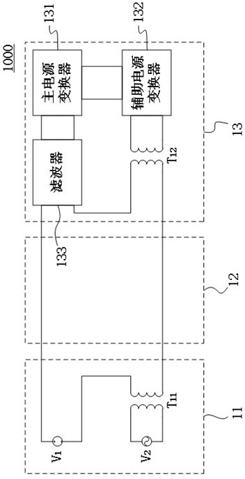
[0033] figure 1 A schematic composition diagram of a first power supply system applied to underwater equipment in the prior art is shown.

[0034] Such as figure 1 As shown, the first power supply system 1000 may include an onshore power source 11 , a first umbilical cable 12 and subsea equipment 13 . Wherein, the shore power supply 11 may include the first power supply V 1 and the second power supply V 2 and the first coupling transformer T 11 .

[0035] where the first...


PUM


Abstract

The present application is a power supply system applied to underwater equipment, including: a first transmission line group, including a first transmission line and a second transmission line, and the first transmission line and the second transmission line transmit the first For electric energy, the first transmission line and the second transmission line transmit the second electric energy in a differential mode; the second transmission line group transmits the first electric energy in a differential mode with the first transmission line group.

Description

technical field [0001] The application belongs to the field of underwater equipment, in particular to a power supply system applied to underwater equipment. Background technique [0002] At present, with the advancement of high-power high-voltage DC electronic technology, high-power and high-efficiency DC transmission systems have become the main way of power supply for underwater equipment. In the HVDC transmission system, the high-voltage input DC power supply at the underwater receiving end needs an auxiliary power supply to start. [0003] The conventional solution is to take energy directly from the high-voltage line. Due to the high input voltage, the converter needs to withstand high voltage stress. The development and design are difficult and the reliability is low. [0004] In order to avoid taking power directly from the high-voltage line, there are currently two main solutions. One of them is to set a battery at the power receiving end, and use the battery to ...

Claims


Application Information

Patent Timeline
Patent Type & Authority Patents(China)
IPC IPC(8): H02J1/10
CPCH02J1/109
Inventor 魏建仓张伟强张金良申国彬王林广
Owner 天津深之蓝能源科技有限公司
Why Eureka
Try Eureka