
Die cutting roller with height-adjustable rigidity-controllable cutter

A die-cutting roller and tool technology, applied in metal processing and other directions, can solve the problems of large friction resistance, small thickness adjustment, and easy damage to tools, so as to reduce the frequency of tool damage, improve production efficiency, and prevent tool damage.

Pending Publication Date: 2021-08-27
HUAQIAO UNIVERSITY
View PDF0 Cites 0 Cited by
  • Summary
  • Abstract
  • Description
  • Claims
  • Application Information

AI Technical Summary

Problems solved by technology

[0003] The die-cutting machine is a device for die-cutting or embossing cardboard according to the required size and shape. Its working parts are mainly die-cutting rollers and support rollers. Corrugated cardboard is conveyed between the die-cutting rollers and the supporting rollers. The cutting tool die-cuts the cardboard, but the thickness of the corrugated cardboard varies with the number of layers. It is necessary to adjust the distance between the die-cutting roller and the support roller to make the corrugated cardboard of different thicknesses achieve the ideal die-cutting effect. At present, the adjustment of the die-cutting roller Both are adjusted by the motor through the screw structure. The frictional resistance of the screw structure adjustment is large, and a lot of electric energy is wasted during adjustment. Moreover, due to the small thickness adjustment, the screw adjustment control is not accurate, and it is still difficult to adjust to a suitable distance.
[0004] At present, there are many die-cutting roller structures on the market, but the production efficiency of the die-cutting machine is limited due to the easy damage of the cutter, the complicated replacement process and the easy breakage of the shaft body.

Method used


Image

  • Die cutting roller with height-adjustable rigidity-controllable cutter
  • Die cutting roller with height-adjustable rigidity-controllable cutter
  • Die cutting roller with height-adjustable rigidity-controllable cutter

Examples


Embodiment Construction

[0027] The following will clearly and completely describe the technical solutions in the embodiments of the present invention in conjunction with the accompanying drawings in the embodiments of the present invention; obviously, the described embodiments are only part of the embodiments of the present invention, not all embodiments, based on The embodiments of the present invention and all other embodiments obtained by persons of ordinary skill in the art without making creative efforts belong to the protection scope of the present invention.

[0028] In the description of the present invention, it should be noted that the orientations or positional relationships indicated by the terms "upper", "lower", "inner", "outer", "top / bottom" etc. are based on the orientations shown in the drawings Or positional relationship is only for the convenience of describing the present invention and simplifying the description, but does not indicate or imply that the device or element referred t...


PUM


Abstract

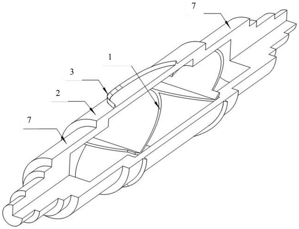
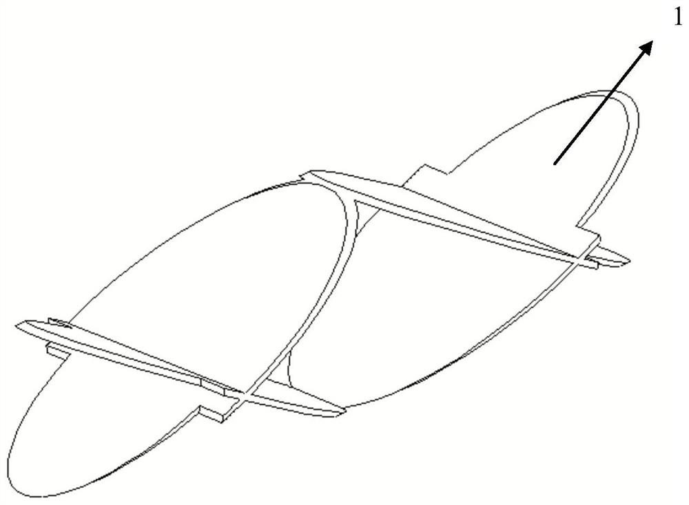
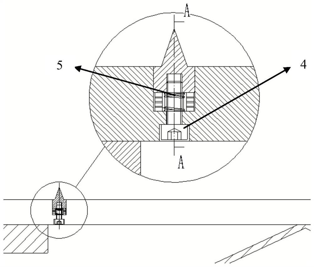
The invention provides a die cutting roller with an height-adjustable rigidity-controllable cutter. The die cutting roller comprises shaft heads arranged at the two axial ends of the die cutting roller, a cutter rest arranged between the shaft heads at the two ends, a cutter fixed to the cutter rest and an inner support arranged inside the die cutting roller, wherein the inner support is used for connecting the tool rest to the shaft heads at two ends, the cutter is connected to the cutter rest through a negative Poisson's ratio chiral material, and the cutter has the moving freedom degree in the radial direction of the die cutting roller. The die cutting roller has the advantages that efficient slicing is achieved, and meanwhile the requirement for light weight is met.

Description

technical field [0001] The invention relates to a high-performance engineering structure, which is mainly used in the die-cutting machine industry, more precisely, it is a die-cutting roller with the function of high-efficiency and light-weight protection of knives Background technique [0002] As far as the processing and cutting of the existing strip-shaped finished product strips are concerned, a die-cutting machine is often used. Die-cutting machine is also called beer machine, cutting machine, CNC stamping machine, mainly used for die-cutting of some corresponding non-metallic materials, self-adhesive, EVA, double-sided adhesive, electronics, mobile phone rubber pad, etc. breaking), indentation and bronzing operations, lamination, automatic waste discharge, die-cutting machines use steel knives, metal molds, steel wires (or templates carved from steel plates), and apply a certain pressure through the embossing plate to print or The cardboard is rolled and cut into cert...

Claims


Application Information

Patent Timeline
Patent Type & Authority Applications(China)
IPC IPC(8): B26F1/44
CPCB26F1/44B26F2001/4463
Inventor 李昆塬张勇
Owner HUAQIAO UNIVERSITY
Learn More